
Page 507 - Cam Design Handbook
P. 507
THB14 9/19/03 7:58 PM Page 495
SPECIAL CAM MECHANISMS 495
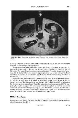
FIGURE 14.45. Computing mechanism cams. (Courtesy Ford Instrument Co., Long Island City,
N.Y.).
to analog computers, cams are often used as correcting devices. In this manner, increased
accuracy is obtained from the mechanisms.
The first step in the design of analog computers is the selection of the output scale, the
input scale being fixed by the fact that the cam rotates usually less than 360° for the
full range. The scale choice is an important consideration. From the standpoint of accu-
racy, it is desirable to have the scale as large as possible, i.e., as few units per inch per
revolution as possible. In this manner, backlash and dimensional accuracy will have a
lesser effect.
The second step is to establish the cam size and the sense of the follower movement,
i.e., whether to move outward or inward for increasing values. This is chosen so that the
steepest portion of the function curve is at the cam outer radius, permitting smaller cams
for the same pressure angle limit. Generally, a maximum pressures angle of 30° is sug-
gested, but angles as high as 45° have been successfully applied. In addition, the reader
should beware of undercutting (see Chap. 6). This detrimental condition may be allevi-
ated by increasing cam size or reducing the output scale. Figure 14.45 shows some com-
puting mechanism cams used for precision machinery applications.
14.28.1 Cam Types
In computers, we denote the basic function of motion relationship between nonlinear
related parameters X and Y as
F X
Y = (). (14.22)