
Page 510 - Cam Design Handbook
P. 510
THB14 9/19/03 7:59 PM Page 498
498 CAM DESIGN HANDBOOK
C x 1
R = u Ú XdX
R w
CX 2
= (14.24)
2 R
w
since X is any arbitrary endpoint. Therefore, the output is proportional to the square of the
input cam rotation. It should be noted that offsetting the follower wheel from the cam axis
would improve the force distribution of the mechanism. For the Archimedes spiral, it can
be shown that an offset equal to the lead per radian will permit the follower wheel to be
tangent to the spiral at all points. The form of this spiral is an involute.
The limitation of the cam discussed occurs when successive turns allow insufficient
clearance for the follower. This condition can be remedied by using several cams in series,
the output of the first supplying the input to the second. For example, suppose the
function to be
2
4
2
Y = X = ( [ X )] . (14.25)
This can be solved by compounding two squaring cams indicated in the equation.
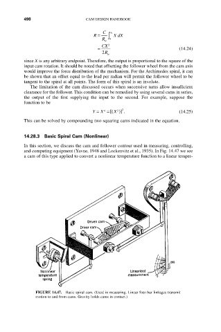
14.28.3 Basic Spiral Cam (Nonlinear)
In this section, we discuss the cam and follower contour used in measuring, controlling,
and computing equipment (Yavne, 1948 and Lockenvitz et al., 1935). In Fig. 14.47 we see
a cam of this type applied to convert a nonlinear temperature function to a linear temper-
FIGURE 14.47. Basic spiral cam. (Used in measuring. Linear four-bar linkages transmit
motion to and from cams. Gravity holds cams in contact.)