
Page 511 - Cam Design Handbook
P. 511
THB14 9/19/03 7:59 PM Page 499
SPECIAL CAM MECHANISMS 499
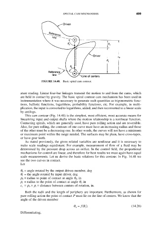
FIGURE 14.48. Basic spiral cam contour.
ature reading. Linear four-bar linkages transmit the motion to and from the cams, which
are held in contact by gravity. The basic spiral contour cam mechanism has been used in
instrumentation where it was necessary to generate such quantities as trigonometric func-
tions, ballistic functions, logarithms, probability functions, etc. For example, in multi-
plication, the input is converted to logarithms, added, and then reconverted to a linear scale
by antilogs.
This cam contour (Fig. 14.48) is the simplest, most efficient, most accurate means for
linearizing input and output shafts where the motion relationship is a nonlinear function.
Contacting spirals, which are generally used, have pure rolling action and are reversible.
Also, for pure rolling, the contours of one curve must have an increasing radius and those
of the other must be a decreasing one. In other words, the curves will not have a minimum
or maximum point within the range needed. The surfaces may be plain, have cross-tapes,
or have gear teeth.
As stated previously, the given related variables are nonlinear and it is necessary to
make scale readings equidistant. For example, measurement of flow of a fluid may be
determined by the pressure drop across an orifice. In the control field, the proportional
mechanisms for control are linear, and therefore for best results we must again have equal
scale measurements. Let us derive the basic relations for this contour. In Fig. 14.48 we
see the two curves in contact.
Let
q 0 = angle rotated by the output driven member, deg
q i = the angle rotated by input driver, deg
r 0 = radius to point of contact at angle q 0, in
r i = radius to the point of contact at angle q i, in
c e = r 0 + r i = distance between centers of rotation, in.
Both the radii and the length of periphery are important. Furthermore, as shown for
pure rolling action the point of contact P must lie on the line of centers. We know that the
angle of the driven member
f
q
q = (). (14.26)
i
0
Differentiating,