
Page 499 - Cam Design Handbook
P. 499
THB14 9/19/03 7:58 PM Page 487
SPECIAL CAM MECHANISMS 487
pared to the previous cylindrical cam, allowing a smaller follower wheel and thus reduced
inertia. The only shortcoming of this type of groove cam follower is that the backlash
between the roller and groove sides may produce noise, wear, and vibration.
Generally, no auxiliary members, such as locating pins or wedge locks, are necessary
during the dwell periods. The number of index stations on the cam-follower turret should
be eight or more, to give reasonable cam and follower wheel proportions.
Experience has shown that a dwell into the index period is desirable, the chordal dis-
tance being about 0.8 of the cam diameter and the follower diameter about twice the cam
diameter. An average pressure angle of about 30° and a maximum pressure angle as high
as 50° have been successful. In Fig. 14.35b we see a development of this cam track. For
more information refer to Jacobs (1953), who utilized turrets from 24 to 60 inches in diam-
eter weighing 200 to 2000 pounds. For small quantities, SAE 4140 forged steel billets with
a cam track flame-hardened to Rock. C50-60 were chosen.
14.26.4 Spider Cam for Intermittent Motion
The spider cam (Richards, 1940, 1941) derives its name from the appearance of the
follower. This mechanism requires a follower having four or more indexing rollers.
One of its former applications was the feeding of the film in motion-picture projectors.
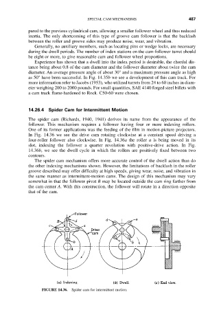
In Fig. 14.36 we see the drive cam rotating clockwise at a constant speed driving a
four-roller follower also clockwise. In Fig. 14.36a the roller a is being moved in its
slot, indexing the follower a quarter revolution with positive-drive action. In Fig.
14.36b, we see the dwell cycle in which the rollers are positively fixed between two
contours.
The spider cam mechanism offers more accurate control of the dwell action than do
the other indexing mechanisms shown. However, the limitations of backlash in the roller
groove described may offer difficulty at high speeds, giving wear, noise, and vibration in
the same manner as intermittent-motion cams. The design of this mechanism may vary
somewhat in that the follower pivot B may be located outside the cam ring farther from
the cam center A. With this construction, the follower will rotate in a direction opposite
that of the cam.
FIGURE 14.36. Spider cam for intermittent motion.