
Page 198 - Carbon Nanotube Fibres and Yarns
P. 198
188 Carbon Nanotube Fibers and Yarns
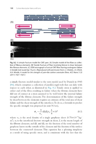
Fig. 8.2 A simple fracture model for CNT yarn. (A) Simple model of the fiber as collec-
tion of fibrous elements. (B) Tensile fracture of fiber involving failure in shear between
the fibrous elements. (C) SEM micrograph of actual CNT fiber having undergone failure
in tensile test (scale bar 10 μm). (Reproduced with permission from J.J. Vilatela, J.A. Elliott,
A.H. Windle, A model for the strength of yarn-like carbon nanotube fibres. ACS Nano 5 (3)
(2011) 1921–1927.)
a simple fracture model similar to the yarn model used by Daniels in 1945
[84], which comprises a collection of parallel, rigid rods that can slide with
respect to each other, as illustrated in Fig. 8.2. Tensile stress is applied to
either end of the fiber, resulting in failure when the fibrous elements have
slid out of contact at a stress assumed to be well below the internal failure
strength of the fibrous elements. The determination of the failure strength
by shear between the elements requires an estimate of the total area of shear
failure and the shear strength of the interfaces. To do so, a formula to predict
the specific strength was proposed (in unit N/tex),
1 L
σ = ΩΩ τ ×10 6 (8.3)
y
ν G 1 2 F 8
−6
where v G is the areal density of a single graphene sheet (0.75 × 10 kg/
2
m ), τ F is the interfacial fracture strength in shear, L is the mean length of
the fibrous elements, and Ω 1 and Ω 2 are the fraction of the total number of
graphene layers on the outside of the element and the fraction of the surface
between the contacted elements. This equation has a pleasing simplicity
as a result of using specific stress, and is consistent with the fact that the