
Page 200 - Carbon Nanotube Fibres and Yarns
P. 200
190 Carbon Nanotube Fibers and Yarns
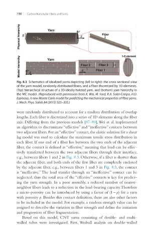
Fig. 8.3 Schematics of idealized yarns depicting (left to right): the cross-sectional view
of the yarn model, randomly distributed fibers, and a fiber discretized by 1D elements.
(Top) hierarchical structure of a 3D ideally twisted yarn, and (bottom) yarn hierarchy in
the MC model. (Reproduced with permission from X. Wei, M. Ford, R.A. Soler-Crespo, H.D.
Espinosa, A new Monte Carlo model for predicting the mechanical properties of fibre yarns.
J. Mech. Phys. Solids 84 (2015) 325–335.)
were randomly distributed to account for a random distribution of overlap
lengths. Each fiber is discretized into a series of 1D elements along the fiber
axis. Differing from the previous models [87–89], Wei et al. implemented
an algorithm to discriminate “effective” and “ineffective” contacts between
two adjacent fibers. For an “effective” contact, the elastic solution for a shear
lag model was used to calculate the maximum tensile stress distribution in
each fiber. If one end of a fiber lies between the two ends of the adjacent
fiber, the contact is defined as “effective,” meaning that load can be effec-
tively transferred between the two adjacent fibers through their interface,
e.g., between fibers 1 and 2 in Fig. 8.3. Otherwise, if a fiber is shorter than
the adjacent fiber, and both ends of the first fiber are completely enclosed
by the adjacent fiber, e.g., between fibers 1 and 3 in Fig. 8.3, the contact
is “ineffective.” The load transfer through an “ineffective” contact can be
neglected, thus the total area of the “effective” contacts is key for predict-
ing the yarn strength. In a poor assembly, a reduced number of nearest-
neighbor fibers leads to a reduction in the load-bearing capacity. Therefore
a micro-porosity can be introduced by using a factor of (1 − p) for a yarn
with porosity p. Besides this contact definition, there are also other factors
to be included in the model. For example, a random strength value can be
assigned to describe the variation in fiber strength and define the initiation
and progression of fiber fragmentation.
Based on this model, CNT yarns consisting of double- and multi-
walled tubes were investigated. First, Weibull analysis on double-walled