
Page 211 - Carbon Nanotube Fibres and Yarns
P. 211
Mechanics modeling of carbon nanotube yarns 201
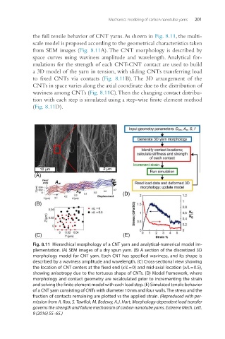
the full tensile behavior of CNT yarns. As shown in Fig. 8.11, the multi-
scale model is proposed according to the geometrical characteristics taken
from SEM images (Fig. 8.11A). The CNT morphology is described by
space curves using waviness amplitude and wavelength. Analytical for-
mulations for the strength of each CNT-CNT contact are used to build
a 3D model of the yarn in tension, with sliding CNTs transferring load
to fixed CNTs via contacts (Fig. 8.11B). The 3D arrangement of the
CNTs in space varies along the axial coordinate due to the distribution of
waviness among CNTs (Fig. 8.11C). Then the changing contact distribu-
tion with each step is simulated using a step-wise finite element method
(Fig. 8.11D).
Fig. 8.11 Hierarchical morphology of a CNT yarn and analytical-numerical model im-
plementation. (A) SEM images of a dry spun yarn. (B) A section of the discretized 3D
morphology model for CNT yarn. Each CNT has specified waviness, and its shape is
described by a waviness amplitude and wavelength. (C) Cross-sectional view showing
the location of CNT centers at the fixed end (x/L = 0) and mid-axial location (x/L = 0.5),
showing anisotropy due to the tortuous shape of CNTs. (D) Model framework, where
morphology and contact geometry are recalculated prior to incrementing the strain
and solving the finite element model with each load step. (E) Simulated tensile behavior
of a CNT yarn consisting of CNTs with diameter 10 nm and four walls. The stress and the
fraction of contacts remaining are plotted vs the applied strain. (Reproduced with per-
mission from A. Rao, S. Tawfick, M. Bedewy, A.J. Hart, Morphology-dependent load transfer
governs the strength and failure mechanism of carbon nanotube yarns. Extreme Mech. Lett.
9 (2016) 55–65.)