
Page 226 - Carbon Nanotube Fibres and Yarns
P. 226
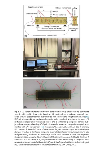
Fig. 9.1  (A) Schematic representation of experimental setup of self-sensing composite
              sample subjected to three-point bending: side and end cross-sectional views of lami-
              nated composite beam sample instrumented with stitched and straight yarn sensors [40].
              (B) Optical image of the experimental setup including mechanical testing system and LCR
              (inductance-capacitance-resistance) reader and a self-sensing composite sample sub-
              jected to three-point bending. (C) Optical image of a laminated composite sample instru-
              mented with CNT yarn sensors [43]. (Source of (A): J.L. Abot, J.C. Anike, J.H. Bills, Z. Onorato,
              D.L. Gonteski, T. Kvelashvili, et al., Carbon nanotube yarn sensors for precise monitoring of
              damage evolution in laminated compos ite materials: latest experimental results and in-situ
              and post-testing validation, in: Proceed ings of the 32nd American Society for Composites
              Conference, West Lafayette, IN, 2017. Source of (B): J.C. Anike, J.L. Abot, J. Bills, D.L. Gonteski, T.
              Kvelashvili, M.S. Alsubhani, et al., Integrated structural health monitoring of composite lami-
              nates using carbon nanotube fibers: static/dynamic loading and validation, in: Proceedings of
              the 21st International Conference on Composite Materials, Xian, China, 2017.)