
Page 229 - Carbon Nanotube Fibres and Yarns
P. 229
220 Carbon Nanotube Fibers and Yarns
0.5
Twist Recovery
0.0
–0.5
∆R/R 0 –1.0
Twist release
–1.5
–2.0
–2.5
0 100 200 300
(A) t (s)
60
Permanent
40 change in R
20
DR/R 0 (%) 0 Release
–20 Recovery
–40
–60
0 1 2 3 4 5 6 7
(B) t (min)
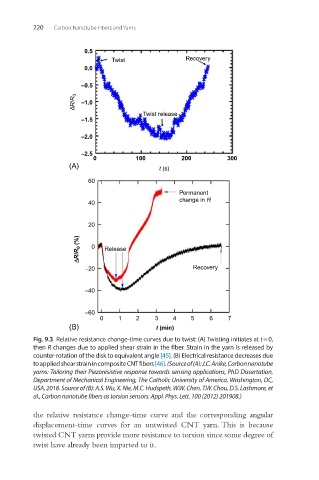
Fig. 9.3 Relative resistance change-time curves due to twist: (A) Twisting initiates at t = 0,
then R changes due to applied shear strain in the fiber. Strain in the yarn is released by
counter- rotation of the disk to equivalent angle [45]. (B) Electrical resistance decreases due
to applied shear strain in composite CNT fibers [46]. (Source of (A): J.C. Anike, Carbon nanotube
yarns: Tailoring their Piezoresistive response towards sensing applications, PhD Dissertation,
Department of Mechanical Engineering, The Catholic University of America, Washington, DC,
USA, 2018. Source of (B): A.S. Wu, X. Nie, M.C. Hudspeth, W.W. Chen, T.W. Chou, D.S. Lashmore, et
al., Carbon nanotube fibers as torsion sensors. Appl. Phys. Lett. 100 (2012) 201908.)
the relative resistance change-time curve and the corresponding angular
displacement-time curves for an untwisted CNT yarn. This is because
twisted CNT yarns provide more resistance to torsion since some degree of
twist have already been imparted to it.