
Page 234 - Carbon Nanotube Fibres and Yarns
P. 234
Sensors based on CNT yarns 225
50
Downward bend Release Upward bend
40
Relative resistance change(%) −10 Downward bend Release
30
20
10
0
−20
Upward bend
−30
−40
0 25 50 75 100
(G) Time (s)
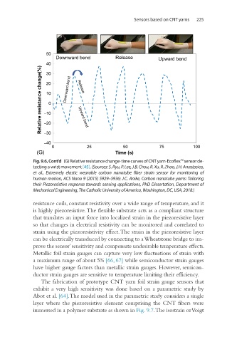
Fig. 9.6, Cont’d (G) Relative resistance change-time curves of CNT yarn-Ecoflex™ sensor de-
tecting a wrist movement [45]. (Sources: S. Ryu, P. Lee, J.B. Chou, R. Xu, R. Zhao, J.H. Anastasios,
et al., Extremely elastic wearable carbon nanotube fiber strain sensor for monitoring of
human motion, ACS Nano 9 (2015) 5929–5936; J.C. Anike, Carbon nanotube yarns: Tailoring
their Piezoresistive response towards sensing applications, PhD Dissertation, Department of
Mechanical Engineering, The Catholic University of America, Washington, DC, USA, 2018.)
resistance coils, constant resistivity over a wide range of temperature, and it
is highly piezoresistive. The flexible substrate acts as a compliant structure
that translates an input force into localized strain in the piezoresistive layer
so that changes in electrical resistivity can be monitored and correlated to
strain using the piezoresistivity effect. The strain in the piezoresistive layer
can be electrically transduced by connecting to a Wheatstone bridge to im-
prove the sensor’ sensitivity and compensate undesirable temperature effects.
Metallic foil strain gauges can capture very low fluctuations of strain with
a maximum range of about 5% [66, 67] while semiconductor strain gauges
have higher gauge factors than metallic strain gauges. However, semicon-
ductor strain gauges are sensitive to temperature limiting their efficiency.
The fabrication of prototype CNT yarn foil strain gauge sensors that
exhibit a very high sensitivity was done based on a parametric study by
Abot et al. [64]. The model used in the parametric study considers a single
layer where the piezoresistive element comprising the CNT fibers were
immersed in a polymer substrate as shown in Fig. 9.7. The isostrain or Voigt