
Page 237 - Carbon Nanotube Fibres and Yarns
P. 237
Piezoresistive CNT Yarn
layer (CNT yarns) Voltage-measuring Voltage-
z
electrode applying
y electrode
x2 q x1
y CNT Yarn x
x
Substrate Orientation
y
x
(C) z
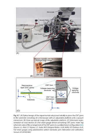
Fig. 9.7 (A) Optical image of the experimental setup used initially to place the CNT yarns
in the substrate consisting of a microscope with an adjustable platform and a vacuum
connection. (B) Close-up optical image of the adjustable platform. (C) Schematic repre-
sentation of cross-section of a foil strain gauge sensor comprising CNT yarns. Inset: Top
schematic view of the arrangement of the CNT yarns in a unidirectional configuration [65].
(Source: J.L. Abot, C.Y. Kiyono, J.C. Anike, M.R. Góngora-Rubio, L.A.M. Mello, V.F. Cardoso, et al.,
Foil strain gauges using piezoresistive carbon nanotube yarn: fabrication and calibration,
Sensors (2) (2018) 464.)