
Page 30 - Carbon Nanotube Fibres and Yarns
P. 30
Yarn production from carbon nanotube forests 23
spread the yarn on the bobbin in an orderly fashion. A computer is used to
coordinate these motions. The machine can be run at twist insertion rate
(spindle speed) up to 7000 rpm.
A series of friction pins can be introduced between the CNT forest
and the spindle on the flyer spinning machine [37]. These pins affect the
spinning process in two ways: increasing the yarn tension and causing the
twist to be inserted into the yarn in steps along the zones separated by the
pins. The increased tension further increases yarn density, leading to a more
compact yarn structure and higher stress-based strength and elastic modulus
but lower breaking strain.
The flyer spinner can also be used to add solvent, polymers, or other
additives while a CNT yarn is being spun [36]. The additives can be conve-
niently applied on the CNT web and forming yarn between the feedstock
forest and the yarn guide, as shown in Fig. 2.7C.
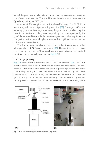
2.3.1.2 Up-spinning
Fig. 2.8 shows what is dubbed as the CSIRO “up-spinner” [38]. The CNT
forest is attached to a spindle that can be rotated at a high speed. The con-
tinuous CNT web drawn from the forest is pulled up (hence the name
up-spinner) to the yarn bobbin while twist is being inserted by the spindle
beneath it. On the up-spinner, the two essential functions of continuous
yarn spinning are carried out independently: twist is inserted by the fast
rotating vertical spindle that carries the feedstock (the CNT forest) while
Fig. 2.8 Main operating elements of the up-spinner.