
Page 118 - Carbon Nanotubes
P. 118
Hemi-toroidal networks in pyrolytic carbon nanotubes 107
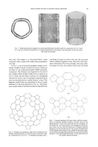
Fig. 3. Molecular graphics images of an archetypal flattened toroidal model of a nanotube with n = 5 and
m = 4 at three different orientations in a plane perpendicular to the paper. Note the points on the rim where
the cusps are located.
ther side. The image is, as discussed below, quite matching p/h pairs in such a way that the curvature
consistent with a single twin-walled tube connected at allows optimal graphene sheet distortion and inter-
one end. sheet interaction. For every p/h pair, the outer cylin-
In Fig. 3, a set of molecular graphics images of mo- der gains an extra two carbon atoms over the inner
lecular models of hemi-toroidal structures, which are
the basis of the archetypal double-walled nanotube,
is depicted. The Schlegel-type diagram for the rim of
the smallest likely double-walled tube is depicted in
Fig. 4, where the fact that it consists of a hexagonal
network in which 5 sets of pentagodheptagon (p/h)
pairs are interspersed in a regular manner is seen. This
g[-1g
diagram results from the connection of five p/h pair
templates of the kind depicted in Fig. 5a. The inside
and outside walls of the hemi-toroid are linked by the
\
\
\ I I I- I I I I
\ L A I
\ i
\ /
\ /
\ i
(b)
Fig. 5. General templates for inner/outer wall rim connec-
tions: a) simplest feasible template (section between the
dashed lines) in which one bond separates the heptagons on
the inside rim, one bond separates the heptagons and penta-
gons across the rim, and two bonds and a hexagon separate
pengatons on the outside rim; b) The overall circumference
of the hemitoroidal structure can readily be increased with-
Fig. 4. Schlegel-type diagram of the hemi-toroidal rim of a out increasing the interwall separation by inserting rn further
double walled nanotube, in which the inner and outer walls hexagon + two half-length bond units of the kind shown in
are connected by a set of n = 5 pentagon/heptagon pairs. the square dashed brackets.