
Page 119 - Carbon Nanotubes
P. 119
I08 A. SARKAR et al.
one. The number of p/h pairs determines the wall sep- workstation operating the Cerius Molecular Mechan-
aration and, for five such pairs, the circumference of ics Programme. The results, at a series of angles (0, 5,
the outer wall gains 10 extra atoms and the difference 10, and 15') to the normal in a plane perpendicular to
in the radius increases by ca. 3.5 A-very close to the the paper, are shown diagrammatically in Fig. 6a. The
optimum graphite interlayer spacing. Furthermore, if associated simulated TEM images for the analogous
a particular template is bisected and further hexago- angles to the electron beam are depicted in Fig. 6b.
nal network inserted at the dashed line, as indicated The model has inner/outer radii of ca. 1.75/2.10 nm
in Fig. 5, then the radii of the connected concentric (Le., 5x and 6x the diameter of waist of C7,J. The
cylinders are easily increased without increasing the structure depicted in the experimentally observed
interwall spacing, which will remain approximately HRTEM image is ca. 3.50/3.85 (Le., ca. lox and llx
0.35 nm, as required for graphite. A structure results c70)*
such as that shown in Fig. 3. These templates gener- As the tube orientation changes, we note that the
ate non-helical structures; however, modified versions interference pattern associated with the rim changes
readily generate helical forms of the kind observed[24]. from a line to an ellipse and the loop structures at the
There is, of course, yet another degree of freedom in apices remain quite distinct. The oval patterns in the
this simple template pattern, which involves splitting observed (Fig. 2) and simulated (Fig. 6) HRTEM im-
the template along an arc connecting the midpoints of ages are perfectly consistent with one another. For this
the bonds between the h/p pairs. This procedure results preliminary investigation, a symmetric wall configu-
in larger inter-wall spacings[24]; the resulting struc- ration was used for simplicity. Hemi-toroid connec-
tures are not considered here. tion of inner and outer tubes with helical structured
We note that in the HRTEM images (Figs. 1 and 2) walls requires somewhat more complicated disposi-
the points b and b' lie at the apices of the long axis of tions of 5/6/7 rings in the lip region[24]. The general
an elliptical line-like image. Our study suggests that validity of the conclusions drawn here is, however, not
this pattern is the HRTEM fingerprint of a hemi- affected. Initial studies of this problem[24] indicate
toroidal link structure joining two concentric graph- that linking between the inner and outer walls is also
ite cylinders, whose radii differ by the graphite not hindered in general.
interlayers separation (ca. 0.35 nm). If the number of The toroids show an interesting change in overall
p/h pairs, n = 5 and the number of insertions m = 4 morphology as they become larger, at least at the
(according to Fig. 4), then the structure shown in Fig. 3 1ip.The hypothetical small toroid shown in Fig. 3a is
is generated. The basic topologically generated struc- actually quite smooth and essentially a fairly rounded
ture was relaxed interactively using a Silicon Graphics structure. As the structures become larger, the strain
- -
I
i
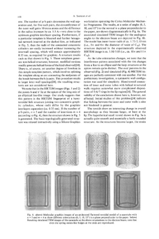
Fig. 6. above) Molecular graphics images of an archetypal flattened toroidal model of a nanotube with
n = 5 and rn = 4 at three different orientations (0,5, 10, 15") in a plane perpendicular to the paper. below)
Resulting simulated TEM images of the nanotube at the above orientations to the electron beam; note that
even the spring onion-like bulges at the ends are reproduced.