
Page 127 - Carbon Nanotubes
P. 127
Properties of buckytubes and derivatives 117
linearly with temperate, which is mainly due to an in- creased. Under an appropriate dc current at a He gas
crease in the carrier concentration. The results show pressure of 500 Torr, the glow discharge was self-
that the bundle of buckytubes may best be described sustained without the necessity of feeding in the graph-
as a semimetal. ite anode. In practice, the rate at which the anode was
consumed was equal to the growth rate of the depos-
3.4 The use of a stable glow discharge for ited rod, thus keeping the electrode spacing and the
the synthesis of carbon nanotubes discharge characteristics constant.
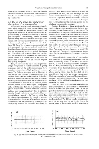
Although the generation of carbon nanotubes by The time dependence of the current across the gap
vapor-phase growth[42], catalytic growth[43,44], and for both the arc discharge and the glow discharge were
corona discharge[45] has been reported, to our knowl- measured during the deposition of buckytubes. The
edge carbon nanotubes in macroscopic quantities are current of the discharge as a function of time was re-
produced only by a carbon-arc discharge in a helium corded using a Hewlett-Packard 7090A Measurement
gas atmosphere. Unfortunately, carbon nanotubes Plotting System. The resultant spectrum for the glow
synthesized by the conventional arc discharge always discharge, shown in Fig. 8 (a), shows no observable
coexist with carbonaceous nanoparticles, possess un- current fluctuation, which demonstrates that the glow
defined morphologies, and have a variety of de- discharge is a continuous process. However, the resul-
fects[46]. One of the serious problems associated with tant plot for the conventional arc discharge, shown in
this technique is that the conventional arc discharge Fig. 8 (b), indicates that the arc current fluctuates with
is a discontinuous, inhomogeneous, and unstable pro- time. An average arc-jump frequency of about 8 Hz
cess. An inhomogeneity of the eIectric field distribution was observed. These results unambiguously demon-
or a discontinuity of the current flow may correlate strate that the conventional arc discharge is a transient
with the incorporation of pentagons and other defects process.
during growth[2]. A natural question is whether the Photographs of the cross-section of two deposited
plasma and current flow can be stabilized to grow rods produced by consuming graphite rods with the
high-quality buckytubes. same diameter ($ inches) at the same dc current
Here, we iintroduce the use of a stable glow dis- (100 A, 20 V) in a He atmosphere at the same pres-
charge for synthesis of carbon nanotubes. It greatly sure (500 Torr) are shown in Fig. 9. Photos (a) and (b)
overcomes many of the problems mentioned above were taken from deposited rods synthesized in the
and allows the synthesis of high-quality carbon nano- glow mode and the arc mode, respectively. The two
tubes. The fullerene generator used in this study is photos clearly indicate that the deposited rod pro-
basically the same chamber we employed for the pro- duced in the glow mode has a more homogeneous
duction of buckyballs and buckytubes described earlier. black core, consisting of an array of bundles of bucky-
However, a modification was made with incorporat- tubes[32], and only a thin cladding. The glow mode
ing a high-voltage feedthrough and a tungsten wire. produced a higher yield of buckytubes than the con-
The wire acted as an extension of the Tesla coil, with its ventional arc mode.
free end pointing toward the arc region. Two graphite Figure 10 shows scanning electron microscopy
rods, with the same diameter of inches, were em- (SEM) micrographs of a cross-section of the deposited
ployed as electrodes. The two electrodes with well- rod synthesized in the glow mode. In Fig. 10 the up-
polished ends were positioned very close to each other per left corner of the micrographs corresponds to the
initially. The glow discharge was stimulated by a co- center of the cross-section of the deposited rod. The
rona discharge triggered by the Tesla coil rather than micrograph shows an evenly distributed array of par-
by striking the anode against the cathode to generate allel bundles of buckytubes from the black region of
a conventional arc discharge. After a plasma was gen- the deposited rod. The thickest bundles with diameters
erated gently over the smooth ends of two electrodes, up to 200 pm were observed for the first time at the
the spacing between the electrodes was slowly in- central region of the deposited rod. It is interesting to
m
+,
.rl
E
3
0 0
Time (sec)
Fig. 8. (a) The current of the glow discharge as a function of time; (b) the current of the arc discharge
as a function of time.