
Page 128 - Carbon Nanotubes
P. 128
11s X. K. WANG et al.
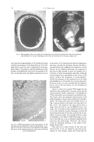
Fig. 9. Photographs of the cross-section of the deposited rods; photos (a) and (b) were taken from deposited
rods produced by the glow discharge and by the conventional arc discharge, respectively.
note that the average diameter of the bundles decreases at the center of the deposited rod and the temperature
towards the perimeter of the deposited rod. The clad- decreases towards the perimeter because the heat is
ding shell around the rod is composed of fused gra- transported by both radiation and conduction via the
phitic flakes. The geometry and the distribution of the He gas. In the cladding shell area, the temperature
bundles in the deposited rod may be interpreted as fol- may not be high enough to form the bundles but is
lows. In the glow mode, the highest temperature occurs sufficient to form fused graphitic materials. Although
several groups have speculated on the effect of the
electric field in the formation of buckytubes[ 13-
16,471, the influence of the temperature on the yield
and distribution of the bundles has not been discussed.
From our results, we may conclude that the tempera-
ture is one of the key factors in the formation of
buckybundles.
Figure 11 shows two typical TEM images for the
deposited rods synthesized in the glow mode and the
conventional arc mode, respectively. Two samples for
TEM observation were prepared in an identical way.
The figures show the dramatic improvement in the
yield and quality of buckytubes synthesized in the glow
mode. The buckytubes and their bundles shown in
Fig. 11 (a) are thicker and longer than that shown in
Fig. 11 (b). The length of the tubes shown here is
larger than the field of view of HREM used in this
study. Our systematic studies indicated that the yield
of the tubes made by the glow discharge is at least 20
times larger than that of the tubes made by the arc dis-
charge. In the arc mode, the jumping of the arc causes
an instability of the electric field which leads to a clo-
sure of the tube tips, so as to minimize dangling bonds
and lower the total energy. Therefore, the conven-
tional arc discharge produces a low yield of low-
Fig. 10. A SEM micrograph of the cross-section of the quality buckytubes.
deposited rod synthesized by the glow discharge shows an im- Note also that a large number of the tube tips,
age of 1/4 of the cross-section of the deposited rod; upper
left corner of the image corresponds to the center of the end shown in Fig. 11 (b), are closed by caps that are po-
of the deposited rod. lygonal or cone-shaped. Iijima has found that the