
Page 56 - Carbonate Sedimentology and Sequence Stratigraphy
P. 56
CHAPTER 3: GEOMETRY OF CARBONATE ACCUMULATIONS 47
Geometry of T, C and M factories cumulations is directly related to the principles of produc-
tion and destruction. A critical element in the carbonate
The three carbonate factories introduced in chapter 2 idf- edifice is a wave-resistant rim at the boundary of the wave-
fer not only by the pathways of precipitation but also by the swept top and the slope shaped by gravity transport – hence
geometry of the respective deposits. The main points are the term “rimmed platforms”.
summarized in Figs 3.18, 3.19, 3.20, 3.21) and discussed in The presence of a rim, often built to sea level, disrupts the
more detail below. seaward-sloping surface normally developed by loose sed-
iment accumulations on a shelf. Rimmed platforms differ
Tfactory. When left to its internal dynamics, the T factory fundamentally from siliciclastic shelves in this respect. The
will strive towards a platform shape, i.e. a flat top near sea growth anatomy of a rimmed platform is that of a bucket –
level and a steep slope on the seaward side; only minuscule a competent, rigid rim protects the loose sediment accumu-
parts of the system will extend into the terrestrial environ- lation of the platform interior (Figs 3.2, 3.3, 3.8, 3.18, 3.19).
ment. This characteristic geometry of tropical carbonate ac-
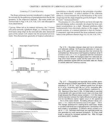
A) slope angle of uppermost rise
Fig. 3.16.— Boundary between slope and rise in siliciclastic
and carbonate settings. A) Frequency distribution of slope an-
frequency % of 0.02 to 0.03 (1.1 – 1.7 ), in agreement with the conclusions
40 gles at the upper limit of the deep-sea fans that constitute the
N=130 continental rise. Note pronounced frequency maximum at tan S
◦
tings show much broader scatter but the lower end of the fre-
0 of Heezen et al. (1959). B) Analogous data from carbonate set-
0.10 tan S
quency distribution agrees with the siliciclastic data set. Based
B)
on seismic data from numerous sources.
40 N=15
0
0.02 0.06 0.10 tan S
Fig. 3.17.— Exponential and sigmoidal slope profiles gener-
A) λ = 0.5 10 km
ated with program STRATA (appendix B). Basic setting: uniform
0.5 km subsidence of 1.67·10 −4 m/yr; sediment supply from left starts
2
2
at 10 m /yr, increasing each My by 2 m /y; nonmarine diffu-
5
sion coefficient K n =1·10 ; marine diffusion coefficient K m =
150. Spacing of time lines 0.3 My. A) Delta builds to sea level
B) λ = 0.1
and progrades with exponentially curved slope and sharp shelf
break because the diffusion decay constant,λ = 0.5; this means
that the transition between the highly-diffusive terrestrial regime
and the low-diffusive marine regime occurs in the uppermost
∼ 20 m of the water column. B) Setting diffusion decay con-
C) λ = 0.5; sea-level fluctuations, amplitude 10 m, period 0.1 My
stant, λ = 0.1, widens the transition zone to the upper ∼ 100 m.
This change, tantamount to lowering storm wave base, results
in rounded shelf break and a sigmoidal profile, particularly in the
early stages of progradation. C) Diffusion decay constant is re-
set to λ = 0.5. Rounded shelf break and sigmoidal profile are
D) as in c, but with influx increasing from 10 to 28 m 2 /y
now generated by small sea-level fluctuations. D) Sharp shelf
break is restored by increased sediment flux. After Schlager
and Adams (2001), modified.