
Page 57 - Carbonate Sedimentology and Sequence Stratigraphy
P. 57
48 WOLFGANG SCHLAGER
T
shoreline Fig. 3.18.— Cartoons of the depositional geometries of the
three carbonate factories. The cross sections show sea level
and wave patterns, bottom morphology and thickness variation
of a typical growth increment. The arrow marks the shoreline.
T factory (green) produces platforms rimmed by reefs or sand
shoals; the factory exports much sediment of all grain sizes; con-
sequently, slopes are steep and rich in shoal-water debris. C
factory (blue) cannot build shallow offshore rims, only scattered
deeper-water skeletal mounds. The geometry of the accumula-
tions is that of a ramp with the highest energy conditions close
to shore. M factory (red) forms convex mounds on gentle slopes
C below the zone of wave action. The mounds develop flat tops
and caps of grainstones where they build into the zone of intense
wave action. The flanks of mounds may be steeper than the max-
◦
imum angle of repose of sand and rubble (about 42 ) because
automicrite cements and stabilizes the flanks.
M
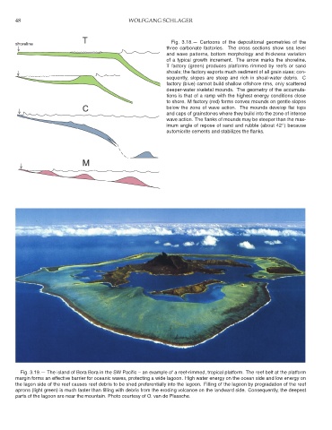
Fig. 3.19.— The island of Bora Bora in the SW Pacific – an example of a reef-rimmed, tropical platform. The reef belt at the platform
margin forms an effective barrier for oceanic waves, protecting a wide lagoon. High water energy on the ocean side and low energy on
the lagon side of the reef causes reef debris to be shed preferentially into the lagoon. Filling of the lagoon by progradation of the reef
aprons (light green) is much faster than filling with debris from the eroding volcanoe on the landward side. Consequently, the deepest
parts of the lagoon are near the mountain. Photo courtesy of O. van de Plassche.