
Page 65 - Carbonate Sedimentology and Sequence Stratigraphy
P. 65
56 WOLFGANG SCHLAGER
FACIES PATTERNS – FROM RAMP TO RIMMED and waves induce a strong onshore currents at the surface
PLATFORM and a weaker (but thicker) return flow near the bottom. Ma-
jor facies boundaries are at sea level, at fair-weather wave
Chapter 3 treated the shore-to-slope profile of shoal-water base and at storm wave base. The first-order facies belts are
carbonate accumulations as a spectrum with two end mem- nearshore sand and offshore mud but the episodic activity
bers – the seaward-dipping profile in equilibrium with wave of storms creates a broad zone of interfingering of shelf mud
action and the rimmed platform with horizontal top, wave- andnearshoresand.
resistant rim and steep slope. The seaward- sloping equilib- Depositional environments on simple carbonate ramps
rium profile is strictly analogous to that of siliciclastic sys- are analogous to Fig. 4.1. Fig. 4.2 shows the principal en-
tems whereas the morphology of rimmed platforms is pecu- vironmental subdivisions on a carbonate ramp as conceived
liar to tropical carbonates the T factory and to the M factory by Burchette and Wright (1992). The analogy with the silci-
where it builds to sealevel. The same situation exists with clastic systems in Figs 4.1 is obvious. Individual cases may
regard to depositional facies. differ from this most simple model by the effects of tidal cur-
Tucker and Wright (1990, p. 49) pointed out that the suc- rents flowing parallel or oblique to shore, and by the pres-
cession of textures and sedimentary structures on carbonate ence of biotic constructions such a mud mounds, shell beds
ramps can be directly matched with siliciclastic shelf mod- and the likes. We shall return to the details of ramp facies af-
els. Fig. 4.1 depicts the most simple siliciclastic shore-to- ter examination of the better known facies belts of rimmed
shelf model. It extends from the beach to the shelf break platforms.
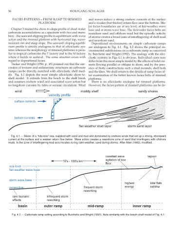
and assumes onshore wind and associated wave action but There is no siliciclastic analogue for rimmed platforms.
no longshore currents by tides or oceanic circulation. Wind However, the facies pattern of rimmed platforms can be de-
wind muddy shelf sandy shores
velocity profile
surface currents
bottom currents
fair-weather mud layer storm sand layer
Fig. 4.1.— Model of a “tide-less” sea, supplied with sand and mud and dominated by onshore winds that set up a strong, shoreward
current at the surface and a weaker return flow below. Wave action creates a nearshore zone of sand that interfingers with offshore
muds. In the zone of interfingering mud accumulates during calm weather, sand during storms. After Allen (1982), modified.
constant wave lagoon
agitation of sea
10's - 100's km
floor
sea level
fair-weather wave base
storm wave base
highest tidal flats
pycnocline frequent storm energy sabkha
reworking
rare tsunami infrequent storm
effects reworking
basin outer ramp mid-ramp inner ramp
Fig. 4.2.— Carbonate ramp setting according to Burchette and Wright (1992). Note similarity with the beach-shelf model of Fig. 4.1.