
Page 629 - Carrahers_Polymer_Chemistry,_Eighth_Edition
P. 629
592 Carraher’s Polymer Chemistry
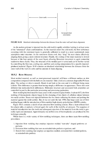
Outer walls
Increased chain
orientation
FIGURE 18.10 Idealized relationships between the distance from the outer wall and chain alignment.
As the molten polymer is injected into the cold mold it rapidly solidifies locking in at least some
of the “orientated” chain conformations. As the material enters the cold mold, the fl ow turbulence
occurring with the outermost layers is generally sufficient to result in a more randomized, more
amorphous outer structure. As the outermost chains cool, they “drag” the next chains effectively
aligning them giving a more ordered structure. Finally, the cooling of the inner material is slowed
because of the heat uptake of the outer layers allowing Brownian movement to again somewhat
randomize these chains. Thus, the structure of the molded part is varied and can be further varied
by controlling the flow rate, cooling rate, and flow and cooling temperatures for a specifi c injected-
produced material. Figure 18.10 contains an idealized relationship between the distance from the
outer wall of the wall of a tube and the amount of chain aligning.
18.9.2 BLOW MOLDING
Most molded material, as well as most processed material, will have a different surface or skin
composition compared with the bulk or core material. Take a look at a common disposable PS foam
plate. The surface or skin is smooth. Break it and look at the core and it is different being more
cellular. This difference is greater than having simply a difference in appearance. There also exist
different fine molecular-level differences. Molecular structure and associated bulk properties are
controlled in part by the particular processing and processing particulars.
Blow molding has been used for many years in the creation of glass bottles. In about 1872, the blow
molding of thermoplastic objects began by the clamping of two sheets of cellulose nitrate between
two mold cavities. Steam was injected between the two sheets softening the sheets and pushing the
material against the mold cavities. But, it was not until the late 1950s that large-scale use of blow
molding began with the introduction of blow-molded high-density polyethylene (HDPE) articles.
Figure 18.11 contains a sketch of an extrusion blow-molding scheme. Here a heat-softened hol-
low plastic tube, or parison, is forced again the walls of the mold by air pressure. The sequence of
material introduction into the mold and subsequent rejection of the material from the mold is gen-
erally rapid and automated. Approximately one million tons of thermoplastics are produced by this
technique annually.
While there is a wide variety of blow-molding techniques, there are three main blow-molding
procedures:
1. Injection blow molding that employs injection molded “test-tube” shaped preforms or
parisons
2. Extrusion blow molding that uses an extruded tube preform or parison, and
3. Stretch blow molding that employs an injection molded, extrusion-blow molded preform,
or extruded tube preform
9/14/2010 3:43:40 PM
K10478.indb 592 9/14/2010 3:43:40 PM
K10478.indb 592