
Page 434 - Centrifugal Pumps 2E
P. 434
398 Centrifugal Pumps: Design and Application
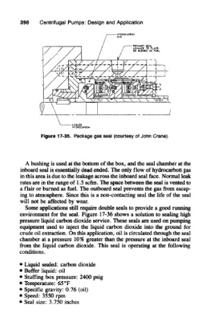
Figure 17-35. Package gas seal (courtesy of John Crane).
A bushing is used at the bottom of the box, and the seal chamber at the
inboard seal is essentially dead ended. The only flow of hydrocarbon gas
in this area is due to the leakage across the inboard seal face. Normal leak
rates are in the range of 1.5 scfm. The space between the seal is vented to
a flair or burned as fuel. The outboard seal prevents the gas from escap-
ing to atmosphere. Since this is a non-contacting seal the life of the seal
will not be affected by wear.
Some applications still require double seals to provide a good running
environment for the seal. Figure 17-36 shows a solution to sealing high
pressure liquid carbon dioxide service. These seals are used on pumping
equipment used to inject the liquid carbon dioxide into the ground for
crude oil extraction. On this application, oil is circulated through the seal
chamber at a pressure 10% greater than the pressure at the inboard seal
from the liquid carbon dioxide. This seal is operating at the following
conditions.
• Liquid sealed: carbon dioxide
• Buffer liquid: oil
• Stuffing box pressure: 2400 psig
• Temperature: 65 °F
• Specific gravity: 0.76 (oil)
• Speed: 3550 rpm
• Seal size: 3.750 inches