
Page 138 - Centrifugal Pumps Design and Application
P. 138
116 Centrifugal Pumps: Design and Application
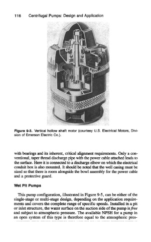
Figure 9-3. Vertical hollow shaft motor (courtesy U.S. Electrical Motors, Divi-
sion of Emerson Electric Co.).
with bearings and its inherent, critical alignment requirements. Only a con-
ventional, taper thread discharge pipe with the power cable attached leads to
the surface. Here it is connected to a discharge elbow on which the electrical
conduit box is also mounted. It should be noted that the well casing must be
sized so that there is room alongside the bowl assembly for the power cable
and a protective guard.
Wet Pit Pumps
This pump configuration, illustrated in Figure 9-5, can be either of the
single-stage or multi-stage design, depending on the application require-
merits and covers the complete range of specific speeds. Installed in a pit
or inlet structure, the water surface on the suction side of the pump is free
and subject to atmospheric pressure. The available NPSH for a pump in
an open system of this type is therefore equal to the atmospheric pres-