
Page 140 - Centrifugal Pumps Design and Application
P. 140
118 Centrifugal Pumps: Design and Application
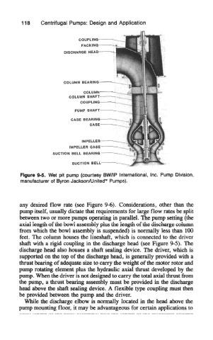
Figure 9*5. Wet pit pump (courtesy BW/IP international, inc. Pump Division,
manufacturer of Byron Jackson/United™ Pumps).
any desired flow rate (see Figure 9-6). Considerations, other than the
pump itself, usually dictate that requirements for large flow rates be split
between two or more pumps operating in parallel. The pump setting (the
axial length of the bowl assembly plus the length of the discharge column
from which the bowl assembly is suspended) is normally less than 100
feet. The column houses the lineshaft, which is connected to the driver
shaft with a rigid coupling in the discharge head (see Figure 9-5). The
discharge head also houses a shaft sealing device. The driver, which is
supported on the top of the discharge head, is generally provided with a
thrust bearing of adequate size to carry the weight of the motor rotor and
pump rotating element plus the hydraulic axial thrust developed by the
pump. When the driver is not designed to carry the total axial thrust from
the pump, a thrust bearing assembly must be provided in the discharge
head above the shaft sealing device. A flexible type coupling must then
be provided between the pump and the driver.
While the discharge elbow is normally located in the head above the
pump mounting floor, it may be advantageous for certain applications to