
Page 151 - Chalcogenide Glasses for Infrared Optics
P. 151
Conventional Lens Fabrication and Spherical Surfaces 127
resistance to humidity, adherence, and resistance to abrasion. All AMI
films are tested according to MIL-PRF 13830B, Appendix C 3 8.2, the
24-h humidity test, 3841 the severe abrasion test, 3842 the moderate
abrasion test, and 385 the adhesion test. The humidity test is carried
out in a commercially available environmental chamber. Adhesion is a
tape pull test using a designated tape. Both abrasion tests are surface
rubs under exact conditions observing damage.
During the coating operation, extra pieces are included to serve
as witness samples. Quality tests are performed on these. If the wit-
ness samples pass, the coated parts may be approved for delivery.
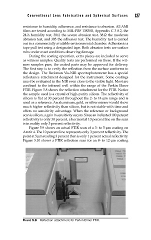
The first step is to verify the reflection from the surface conforms to
the design. The Beckman Vis-NIR spectrophotometer has a special
reflectance attachment designed for the instrument. Some coatings
must be evaluated in the NIR even close to the visible light. Most are
confined to the infrared well within the range of the Perkin Elmer
FTIR. Figure 5.8 shows the reflection attachment for the FTIR. Notice
the sample used is a crystal of high-purity silicon. The reflectivity of
silicon is flat at 30 percent throughout the 2- to 14-µm range and is
used as a reference. An aluminum, gold, or silver mirror would show
much higher reflectivity than silicon, but is not stable with time and
offers no sensitivity advantage. When the reference or background
scan is silicon, a gain in sensitivity occurs. Since an indicated 100 percent
reflectivity is only 30 percent, a horizontal 10 percent line on the scan
is in reality only 3 percent reflectivity.
Figure 5.9 shows an actual FTIR scan of a 3- to 5-µm coating on
Amtir 4. The 10 percent line represents only 3 percent reflectivity. The
point at 5 µm reading 3 percent then is only 1 percent actual reflectivity.
Figure 5.10 shows a FTIR reflection scan for an 8- to 12-µm coating
FIGURE 5.8 Refl ection attachment for Perkin Elmer FTIR.