
Page 246 - Chalcogenide Glasses for Infrared Optics
P. 246
222 Cha pte r Ni ne
A successful method for heat-treating the CdTe from the plates with
first Cd vapor followed by Te vapor was developed that dramatically
improved infrared transmission. A prism was fabricated from a melt-
grown plate, and the refractive index measured 3 to 12 µm. The
measured values were slightly higher than those measured on Kodak
hot pressed Irtran 6. That result would be expected since Irtran 6 only
has nearly 100 percent density.
9.4 Vacuum Float Zoned Silicon Detector Material
The normal method for growing crystals of silicon, the Czochralski
(Cz) method, in which the crystal is grown from an open melt, suffers
from impurities getting into the melt during the growth process.
Chief among the impurities is carbon coming from graphite parts of
the crystal grower and oxygen from quartz liners containing the silicon
melt. A great advance occurred when TI developed and used the
extreme high-purity vacuum float zone technique. TI used this
method to produce the high-grade silicon required for the “paveway
detector” sensitive to the Yag 1.064-µm laser radiation that made
possible the first laser-guided bombs used by the military. The super-
vision of the growth of this material was one of the responsibilities
held by George Cronin when he was at TI. George Cronin felt that
production of such a specialized silicon was an ideal product for a
small niche company such as AMI. In 1983, he searched around and
located two intact units in California that had been sold off by TI as
surplus equipment. AMI purchased the units and had them moved to
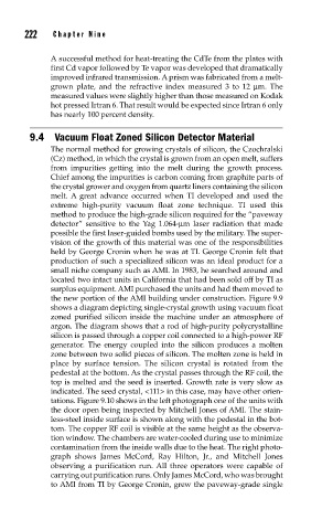
the new portion of the AMI building under construction. Figure 9.9
shows a diagram depicting single-crystal growth using vacuum float
zoned purified silicon inside the machine under an atmosphere of
argon. The diagram shows that a rod of high-purity polycrystalline
silicon is passed through a copper coil connected to a high-power RF
generator. The energy coupled into the silicon produces a molten
zone between two solid pieces of silicon. The molten zone is held in
place by surface tension. The silicon crystal is rotated from the
pedestal at the bottom. As the crystal passes through the RF coil, the
top is melted and the seed is inserted. Growth rate is very slow as
indicated. The seed crystal, <111> in this case, may have other orien-
tations. Figure 9.10 shows in the left photograph one of the units with
the door open being inspected by Mitchell Jones of AMI. The stain-
less-steel inside surface is shown along with the pedestal in the bot-
tom. The copper RF coil is visible at the same height as the observa-
tion window. The chambers are water-cooled during use to minimize
contamination from the inside walls due to the heat. The right photo-
graph shows James McCord, Ray Hilton, Jr., and Mitchell Jones
observing a purification run. All three operators were capable of
carrying out purification runs. Only James McCord, who was brought
to AMI from TI by George Cronin, grew the paveway-grade single