
Page 273 - Chalcogenide Glasses for Infrared Optics
P. 273
248 Cha pte r T e n
~I 1
~I 2
φ 0
φ 0
~I 0
(a)
n 0 n 1 n 2
I 2
I 1
φ 0
φ 0 φ 1
φ 0
I 0
d
(b)
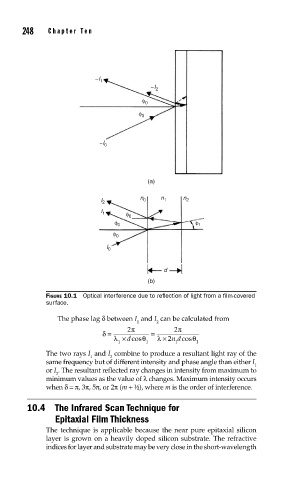
FIGURE 10.1 Optical interference due to refl ection of light from a fi lm-covered
surface.
The phase lag δ between I and I can be calculated from
1 2
δ = 2 π = 2 π
λ × dcos θ 1 λ × 2n dcos θ 1
1
1
The two rays I and I combine to produce a resultant light ray of the
1 2
same frequency but of different intensity and phase angle than either I
1
or I . The resultant reflected ray changes in intensity from maximum to
2
minimum values as the value of λ changes. Maximum intensity occurs
when δ=π, 3π, 5π, or 2π (m + ½), where m is the order of interference.
10.4 The Infrared Scan Technique for
Epitaxial Film Thickness
The technique is applicable because the near pure epitaxial silicon
layer is grown on a heavily doped silicon substrate. The refractive
indices for layer and substrate may be very close in the short-wavelength