
Page 177 - Challenges in Corrosion Costs Causes Consequences and Control(2015)
P. 177
ELECTRICAL UTILITIES 155
Containment Isolation
structure valves
Steam
Steam
turbine
Electricity
Water
Pressure vessel
Generator
Core
Control rods
Water pool
Condenser
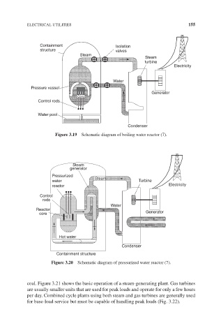
Figure 3.19 Schematic diagram of boiling water reactor (7).
Steam
generator
Pressurized
Steam
water Turbine
reactor Electricity
Control
rods
Water
Reactor
core Generator
Hot water
Condenser
Containment structure
Figure 3.20 Schematic diagram of pressurized water reactor (7).
coal. Figure 3.21 shows the basic operation of a steam-generating plant. Gas turbines
are usually smaller units that are used for peak loads and operate for only a few hours
per day. Combined cycle plants using both steam and gas turbines are generally used
for base-load service but must be capable of handling peak loads (Fig. 3.22).