
Page 101 - Chemical Process Equipment - Selection and Design
P. 101
5.2. PNEUMATIC CONVEYING 73
Gravity-flow Hop
Pickup (a)
Vent
Blower
and Motor
Switch Rotary Valve
Collector a
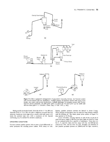
Figure 5.3. Basic equipment arrangements of pneumatic conveying systems. (a) Vacuum system
with several sources and one destination, multiple pickup; (b) pressure system with rotary valve
feeder, one source and several destinations, multiple discharge; (c) pressure system with Venturi
feed for friable materials; (d) pull-push system in which the fan both picks up the solids and
delivers them [after F. J. Gerchow, Chem. Eng. (17 Feb. 1975, p. SS)].
Piping usually is standard steel, Schedule 40 for 3-7 in. IPS and feeders, positive pressure systems are limited to about 12 psig.
Schedule 30 for 8-12 in. IPS. In order to minimize pressure loss and Other feeding arrangements may be made for long distance transfer
abrasion, bends are made long radius, usually with radii equal to 12 with 90-125psig air. The dense phase pulse system of Figure 5.4
times the nominal pilpe size, with a maximum of Xft. Special may operate at 10-30 psig.
reinforcing may be needed for abrasive conditions. Linear velocities, carrying capacity as cuft of free air per lb of
solid and power input as HP/tons per hour (tph) are listed in Table
5.1 as a general guide for a number of substances. These data are
OPERATING COMDIT[ONS
for 4-, 5-, and 6-in. lines; for 8-in. lines, both Sat. and HP/tph are
Vacuum systems usually operate with at most a 6 psi differential; at reduced by 15%, and for 10-in. by 25%. Roughly, air velocities in
lower pressures the carrying power suffers. With rotary air lock low positive pressure systems are 2000 ft/min for light materials,