
Page 100 - Chemical Process Equipment - Selection and Design
P. 100
72 TRANSFER OF SOLIDS
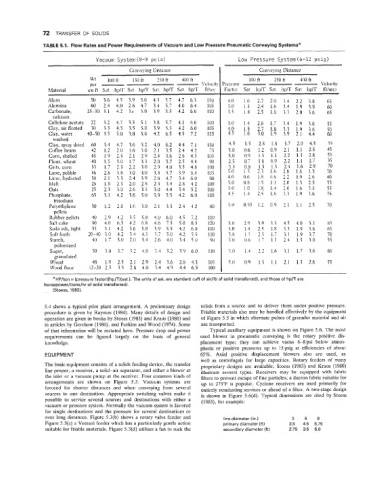
TABLE 5.1. Flow Rates and Power Requirements of Vacuum and Low Pressure Pneumatic Conveying Systemse
Vacuum Systern(8-9 psi4 Low Pressure Systern(6-12 psig)
Conre> ing Ilistauce Con\ e\ iiie Distance
Alum 50 3.6 4.5 3.9 5.0 4.3 5.7 4.7 6.3 1 10 4.0 1.6 2.7 2.0 3.4 2.2 3.8 65
Alumina 60 2.4 4.0 2.8 4.7 3.4 5.7 4.0 6.4 105 5.0 1.1 2.4 1.6 3.4 1.9 3.9 60
Car1)onate. 25-30 3.1 4.2 3.i 5.0 3.9 5.5 4.2 6.0 I10 3.5 1.4 2.5 1.8 3.3 2.0 3.6 65
calcium
Celluloseacetatc 22 3.2 4.7 3.5 5.1 3.8 5.7 4.1 6.0 I00 3.0 1.4 2.8 1.7 3.4 1.9 3.6 55
Clay,airfluated 30 3.3 4.5 3.5 5.0 3.9 5.5 4.2 6.0 105 4.0 1.5 2.7 1.8 3.3 1.9 3.6 50
Clay,water 40-50 3.5 5.0 3.8 5.6 4.2 6.5 4.5 7.2 115 4.5 1.6 3.0 1.9 3.9 2.1 4.4 60
washed
--
Clay. spray dried 60 3.4 4.7 3.6 5.2 4.0 6.2 4.4 7.1 110 4.3 1.5 2.8 1.8 3.7 2.0 4.3 55
Coffee beans 42 1.2 2.0 1.6 3.0 2.1 3.5 2.4 4.2 I> 5.0 0.6 1.2 0.9 2.1 1.1 2.5 45
Corn,shelled 45 1.9 2.5 2.1 2.Y 2.4 3.6 2.8 4.3 Ill5 5.0 0.9 1.5 1.1 2.2 1.3 2.6 55
Flour, wheat 40 1.5 3.0 1.7 ?.3 2.0 3.7 2.5 4.4 90 2.5 0.7 1.8 0.9 2.2 1.1 2.7 35
Grits, corn 33 1.7 2.5 2.2 3.0 2.9 4.0 3.5 4.8 100 3.5 0.8 1.5 1.3 2.4 1.6 2.9 70
Lime, pebble 56 2.8 3.8 3.0 4.0 3.4 4.7 3.9 5.4 I05 5.0 1.3 2.3 1.6 2.8 1.8 3.3 70
Lirne.hydrated 30 2.1 3.3 2.4 3.9 2.8 4.7 3.4 6.0 90 4.0 0.6 1.8 0.8 2.2 0.9 2.6 40
hlalt 28 1.8 2.5 2.0 2.8 2.3 3.4 2.8 4.2 100 5.0 0.8 1.5 1 1 2.0 1.3 2.5 55
Oats 25 2.3 3.0 2.6 3.5 3.0 4.4 3.4 5.2 100 5.0 1.0 1.8. 1.4 2.6 1.6 3.1 55
Phosphate, 65 3.1 4.2 3.6 5.0 3.9 5.5 4.2 6.0 I10 4.5 1.4 2.5 1.8 3.3 1.9 3.6 75
trisodium
Polyethylene 30 1.2 2.0 1.6 3.0 2.1 3.5 2.4 4.2 80 5.0 0.55 1.2 0.9 2.1 1.1 2.5 70
pellets
Rubber pellets 40 2.9 4.2 3.5 5.0 4.0 6.0 4.5 7.2 I 10
Salt cake 90 4.0 6.5 4.2 6.8 4.6 7.5 5.0 8.5 120 5.0 2.9 3.9 3.5 4.5 4.0 5.1 83
Sodaash,light 35 3.1 4.2 3.6 5.0 3.9 5.5 4.2 6.0 I10 5.0 1.4 2.5 1.8 3.3 1.9 3.6 65
Soft feeds 20-40i.0 4.2 34 4.5 3.7 5.0 4.2 5.5 1 IO 3.8 1.; 2.5 1.7 i.! 1.9 3.7 70
Starch. 40 1.7 3.0 2.0 3.4 2.6 4.0 3.4 5.0 YO 3 0 0.8 1 7 1.1 2.4 1.5 3.0 55
pulverized
Sugar, 50 3.0 3.7 3.2 4.0 3.4 5.2 3.9 6.0 ! 10 5.0 1.4 2.2 1.6 3.1 1.7 3.6 60
granulated
Wheat 48 1.9 2.5 2.1 2.9 2.4 3.6 2.8 4.3 105 5.0 0.9 1.5 1.1 2.1 1.3 2.6 55
Wood flour 12-202.5 3.5 2.8 4.0 3.4 4.9 1.4 6.5 100
a HP/ton = (pressure factor)(hp/T)(sat.). The units of sat. are standard cufI of air/lb of solid transferred), and those of hp/T are
horsepower/(tons/hr of solid transferred).
(Stoess, 1983).
5.4 shows a typical pilot plant arrangement. A preliminary design solids from a source and to deliver them under positive pressure.
procedure is given by Raymus (1984). Many details of design and Friable materials also may be handled effectively by the equipment
operation are given in books by Stoess (1983) and Kraus (1980) and of Figure 5.5 in which alternate pulses of granular material and air
in articles by Gerchow (1980), and Perkins and Wood (1974). Some are transported.
of that information will be restated here. Pressure drop and power Typical auxiliary equipment is shown on Figure 5.6. The most
requirements can be figured largely on the basis of general used blower in pneumatic conveying is the rotary positive dis-
knowledge. placement type; they can achieve vacua 6-8psi below atmos-
pheric or positive pressures up to 15psig at efficiencies of about
EQUIPMENT 65%. Axial positive displacement blowers also are used, as
well as centrifugals for large capacities. Rotary feeders of many
The basic equipment consists of a solids feeding device, the transfer proprietary designs are available; Stoess (1983) and Kraus (1980)
line proper, a receiver, a solid-air separator, and either a blower at illustrate several types. Receivers may be equipped with fabric
the inlet or a vacuum pump at the receiver. Four common kinds of filters to prevent escape of fine particles; a dacron fabric suitable for
arrangements are shown on Figure 5.3. Vacuum systems are up to 275°F is popular. Cyclone receivers are used primarily for
favored for shorter distances and when conveying from several entirely nondusting services or ahead of a filter. A two-stage design
sources to one destination. Appropriate switching valves make it is shown in Figure 5.6(d). Typical dimensions are cited by Stoess
possible to service several sources and destinations with either a (1983), for example:
vacuum or pressure system. Normally the vacuum system is favored
for single destinations and the pressure for several destinations or
over long distances. Figure 5.3(b) shows a rotary valve feeder and line diameter (in.) 3 5 8
Figure 5.3(c) a Venturi feeder which has a particularly gentle action primary diameter (ft) 3.5 4.5 6.75
suitable for friable materials. Figure 5.3(d) utilizes a fan to suck the secondary diameter (ft) 2.75 3.5 5.0