Page 102 - Chemical Process Equipment - Selection and Design
P. 102

74  TRANSFER  OF  SOLIDS
                                                                  and bulk density is due to Gerchow (1980) and is

                                                                                             R/min
                                                                            Line length
                                                                               (ft)   55 Ib/cuft   55-85   85-115
                                                                               200      4000   5000   6000
                                                                               500      5000   6000   7000
                                                                               1000     6000   7000   8000
                                                                      Conveying capacity expressed as vol % of  solids in the stream
                                                                  usually is  well under  5 ~01%. From  Table 5.1,  for example, it is
                                                                   about 1.5% for alumina and 6.0% for polystyrene pellets, figured at
                                                                   atmospheric pressure;  at  12 psig these percentages will be  roughly
                                                                   doubled, and at subatmospheric pressures they will be lower.

                                                                   POWER CONSUMPTION AND PRESSURE DROP
                                                                   The power consumption is made up of  the work of  compression of
                                                                   the  air  and  the  frictional losses due to the  flows  of  air  and  solid
                                                                   through the line. The work of  compression of  air at a flow rate rnL
                                                                   and CJC,  = 1.4 is given by
                                                                      w, = 3.5(53.3)(7‘ + 460)rn~[(P2/P1)0~2s57 11   (ft lbf/sec)
                                                                                                  -
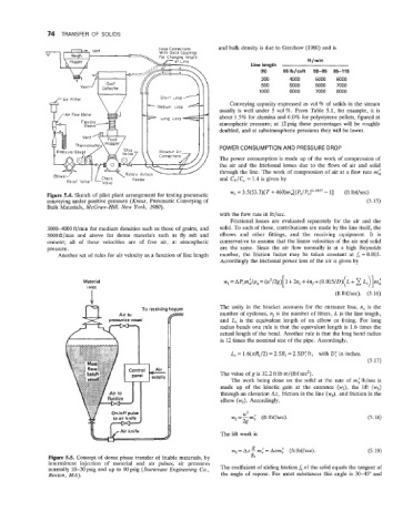
               Figure 5.4.  Sketch of  pilot plant arrangement for testing pneumatic
               conveying under positive pressure (Kraus, Pneumatic Conveying of                                (5.15)
               Bulk Materials, McGraw-Hill, New  York, 1980).
                                                                   with the flow rate in lb/sec.
                                                                      Frictional losses are  evaluated  separately for  the  air  and  the
               3000-4000 ft/min for medium densities such as those of  grains, and   solid. To each of these, contributions are made by the line itself, the
               5000ft/min  and  above  for  dense  materials  such  as  fly  ash  and   elbows  and  other  fittings,  and  the  receiving  equipment.  It  is
               cement;  all  of  these  velocities  are  of  free  air,  at  atmospheric   conservative to assume that the linear velocities of  the air and solid
               pressure.                                           are  the  same.  Since the  air  flow  normally  is  at  a  high  Reynolds
                  Another set of  rules for air velocity as a function of  line length   number,  the  friction  factor  may  be  taken  constant  at  fa  = 0.015.
                                                                   Accordingly the frictional power loss of  the air is given by
                            -

                                                                                      [
                          Material                                  w,=APlrnL/p,=  (u2/2g)  1+2n,+4nf+(0.015/D)(L+c  Li)]rnL
                           inlet
                            1                                                                        (ft lbf/sec).  (5.16)
                           rCI              To receiving hopper    The unity in  the  bracket  accounts for  the  entrance loss,  n,  is  the
                                     Air to                        number of  cyclones, nf is the number of  filters, L is the line length,
                                  pressurize vessel                and  Lt is  the  equivalent length  of  an  elbow  or  fitting. For  long
                                                                   radius bends one rule is that  the equivalent length is 1.6 times the
                                                                   actual length of  the bend. Another rule is that the long bend radius
                                                                   is 12 times the nominal size of  the pipe. Accordingly,

                                                                      Li = 1.6(nRj/2) = 2.5Rj = 2.5D;ft,  with D;  in inches.
                                                                                                               (5.17)
                                                                   The value of g is 32.2 ft lb m/(lbf sec’).
                                                                      The work  being done on the solid at the  rate  of  rnflblsec is
                                                                   made  up  of  the  kinetic  gain  at  the  entrance  (w2), the  lift  (w,)
                                                                   through an elevation Az, friction in the line (w4),  and friction in the
                                                                   elbow (w5). Accordingly,

                                                                      w --mi   (ft lbf/sec).                   (5.18)
                                                                          UZ
                                                                       2-2g
                                     Air knife                     The lift work is

                                                                            g
                                                                      w,  = Az - rn,‘ = Azrn,’   (ft lbf/sec).   (5.19)
                Figure 5.5.  Concept of  dense phase transfer of  friable materials, by   gc
               intermittent  injection  of  material  and  air  pulses,  air  pressures
               normally 10-30 psig and up to 90 psig  (Sturtevant Engineering  Co.,   The coefficient of  sliding friction f, of the solid equals the tangent of
                Boston,  MA).                                      the  angle of  repose.  For most substances this angle is 30-45”  and
   97   98   99   100   101   102   103   104   105   106   107