
Page 95 - Chemical Process Equipment - Selection and Design
P. 95
4.3. COMBUSTION GAS TURBINES AND ENGINES 67
Fuel Exhaust
Exhaust 6
Cornpressor Expander
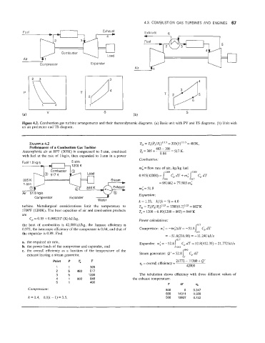
Figure 4.2. Combustion gas turbine arrangements and their thermodynamic diagrams. (a) Basic unit with PV and TS diagrams. (b) Unit with
an air preheater and TS diagram.
EXAMPLE 4.2 T, = q(Pz/P1)1’3-5 305(5)1’3.5 = 483K,
=
Performance of P Combustion Gas Turbine 483 - 305 -
Atmospheric air at 80°F (305K) is compressed to 5 atm, combined Tz= 305 + ~ 0.84 - 517 K.
with fuel at the rate of 1 kg/s, then expanded to 1 atm in a power
Combustion:
5 atm
1200 K
mi =flow rate of air, kg/kg fuel
1200 12Fo
0.975(42000) = 1 Cp dT + miLl, Cp dT
305 K Steam 305
= 991682 + 771985 mi
mi = 51.8
Air 51.8 kg/s Expansion:
Compressor
k = 1.33, k/(k - 1) = 4.0
turbine. Metallurgical considerations limit the temperature to Tk = T3(P4/P1)0.25 1200(0.2)0.z = 802°K
=
1700°F (1200K). The heat capacities of air and combustion products T4 = 1200 - 0.89(1200 - 802) = 846°K
are
Cp = 0.95 + 0.00021T (K) kJ/kg,
Power calculations:
the heat of comblustioin is 42,000 kJ/kg, the furnace efficiency is 517
0.975, the isentropic efficiency of the compressor is 0.84, and that of Compressor: w: = -miAH = -51.8 /jus GdT
the expander is 0.89. Find
= -51.8(216.98) = -11.240 kJ/s
517
a. the required air rate, Expander: w: = -52.8 Cp dT = 52.8(412.35) = 21,772 kJ/s
b. the power loads of the compressor and expander, and
c. the overall efficiency as a function of the temperature of the JLOO 046
exhaust leaving a steam generator. Steam generator: Q‘ = 52.81 Cp dT
Point P p, T 21772 - 11380 + Q’
qt = overall efficiency =
1 1 305 42000
2 5 483 517
3 5 1200 The tabulation shows efficiency with three different values of
4 1 802 846 the exhaust temperature.
5 1 400
T 9s
Compression : 846 0 0.247
600 14311 0.588
k = 1.4, k/(k - 1) = 3.5, 500 19937 0.722