
Page 93 - Chemical Process Equipment - Selection and Design
P. 93
4.3. COMBUSTION GAS TURBINES AND ENGINES 65
EXAMPLE
41.1
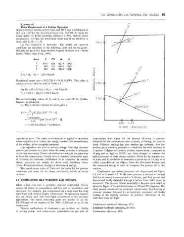
Steam Requirement of a Turbine Operation
Steam is fed to a turbine at 414.7 psia and 825°F and is discharged at
64.7 psia. (a) Find the theoretical steam rate, lb/kWh, by using the
steam tables. (lb) If the isentropic efficiency is 70%, find the outlet
temperature. (c) Find the theoretical steam rate if the behavior is
ideal, with CJC, = 1.33. 1421
(a) The expansion is isentropic. The initial and terminal
conditions are identified in the following table and on the graph.
The data are read off a large Mollier diagram (Keenan et al., Steam
Tables, Wiley, New York, 1969).
Point P TOF N s
1 614.7 825 1421.4 1.642
2 64.7 315 1183.0 1.642
3 64.7 445 1254.5 1.730 M
-1
\
3
AHs = H2 -HI = -238.4 Btu/lb +
M
>
Theoretical steam rate = 3412i238.4 = 14.31 lb/kWh. This value is Q
checked exactly with th'e data of Table 4.3. 2 1255
I
k-
z
(b) E& -HI =0.7(H2 - HI) = -166.9 Btu/lb W
H3 = 1421.4 - 166.9 = 1254.5 Btu/lb
The corresponding values of & and S, are read off the Mollier 1783
diagram, as tabulated.
(c) The isentropic relation for ideal gases is
k
AH=- Rq[(Pz/q)(k-')'k - 11
k-1
- 1.987(1285) [(64.7/614.7)0-25 - 11
-
0.25
1-64 1.73
ENTROPY , BTU/( LB) (F)
combustion gases. The name turboexpander is applied to machines transmission lines where the low thermal efficiency is counter-
whose objective is to reduce the energy content (and temperature) balanced by the convenience and economy of having the fuel on
of the stream, as for cryogenic purposes. hand. Offshore drilling rigs also employ gas turbines. Any hot
Gas expanders are used to recover energy from high pressure process gas at elevated pressure is a candidate for work recovery in
process gas streams in a plant when the lower pressure is adequate a turbine. Offgases of catalytic cracker regenerators, commonly at
for further processing. Power calculations are made in the same way 45psig and as high as 1250"F, are often charged to turbines for
as those for compressors. Usually several hundred horsepower must partial recovery of their energy contents. Plants for the manufacture
be involved for economic justification of an expander. In smaller of nitric acid by oxidation of ammonia at pressures of 100 psig or so
plants, pressures are simply let down with throttling valves utilize expanders on the offgases from the absorption towers, and
(Joule-Thomson) without attempt at recovery of energy. the recovered energy is used to compress the process air to the
The specification sheet of Table 4.4 has room for the process reactors.
conditions and some of the many mechanical details of steam Combustion gas turbine processes are diagrammed on Figure
turbines. 4.2 and in Example 4.2. In the basic process, a mixture of air and
fuel (or air alone) is compressed to 5-10 atm, and then ignited and
MBUSTlON GAS TURBINES AND ENGINES burned and finally expanded through a turbine from which power is
recovered. The process follows essentially a Brayton cycle which is
When a low cost fuel is available, internal combustion drivers shown in Figure 4.2 in idealized forms on TS and PV diagrams. The
surpass all others in compactness and low cost of installation and ideal process consists of an isentropic compression, then heating at
operation. FOT example, gas compression on a large scale has long constant pressure followed by an isentropic expansion and finally
been done with integral engine compressors. Reciprocating engines cooling at the starting pressure. In practice, efficiencies of the
also are widelly used with centrifugal compressors in low pressure individual steps are high:
applications, but speed increasing gears are needed to up the
300-600 rpm of the engines to the 3000-10,000 rpm or so of the
compressor. Compressor isentropic efficiency, 85%
Process applications of combustioin gas turbines are chiefly Expander isentropic efficiency, 85-90%
to driving pumps and compressors, particularly on gas and oil Combustion efficiency, 98%