
Page 88 - Chemical Process Equipment - Selection and Design
P. 88
60 PROCESS CONTROL
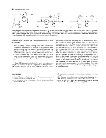
Figure 3.24. Control of positive displacement compressors, rotary and reciprocating. (a) Flow control with variable speed drives. (b) Pressure
control with bypass to the suction of the compressor. (c) Reciprocating compressor. SC is a servomechanism that opens some of suction
valves during discharge, thus permitting stepwise internal bypass. The clearance unloader is controllable similarly. These built-in devices may
be supplemented with external bypass to smooth out pressure fluctuations.
acceptable limits. Two other aids are available to control of recip- atmospheric. Mechanical pumps are used for small capacities, steam
rocating units. jet ejectors for larger ones. Ejectors also are used as ther-
mocompressors to boost the pressure of low pressure steam to an
Valve unloading, a process whereby some of the suction valves intermediate value. Control of suction pressure with either mech-
remain open during discharge. Solenoid or pneumatic unloaders anical or jet pumps is by either air bleed [Fig. 3.5(a)] or suction
can be operated from the output of a control instrument. The line throttling [Fig. 3.5(c)]; air bleed is the more economical process.
stepwise controlled flow rate may need to be supplemented with Up to five jets in series are used to produce high vacua. The steam
controlled external bypass to smooth out pressure fluctuations. from each stage is condensed by direct contact with water in baro-
Clearance unloaders are small pockets into which the gas is metric condensers or in surface condensers; condensation of steam
forced on the compression stroke and expands into the cylinder from the final stage is not essential to performance but only to avoid
on the return stroke, thus preventing compression of additional atmospheric pollution. In a single stage ejector, motive steam flow
gas. cannot be reduced below critical flow in the diffuser, and water to
the barometric condenser must not be throttled below 30-50% of
Figure 3.24 shows control schemes for rotary and reciprocating the maximum if proper contacting is to be maintained. Control by
compressors. Vacuum pumps are compressors operating between a throttling of steam and water supply, as on Figure 3.5(b), is subject
low suction pressure and a fixed discharge pressure, usually to these limitations.
REFERENCES 3. B. Liptak, Instrumentation in the Process Industries, Chilton, New York,
1973.
1. Chemical Engineering Magazine, Practical Process Instrumentation and 4. F.G. Shinskey, Process Control Systems, McGraw-Hill, New York, 1979.
Control, McGraw-Hill, New York, 1980. 5. F.G. Shinskey, Distillation Contro6, McGraw-Hill, New York, 1984.
2. D.M. Considine, Process Instruments and Controls Hamfbook, McGraw- 6. M.R. Skrokov (Ed.), Mini- and Microcomputer Control in Industrial
Hill, New York, 198.5. Processes, Van Nostrand Reinhold, New York, 1980.