
Page 86 - Chemical Process Equipment - Selection and Design
P. 86
58 PROCESS CONTROL
W
Separator
Reactor *
Liquid
Water
-_
:$ Stripper - -
Stripping
Steam
Reactor
\ I Air Preheater Steam
Oil Charge at
Controlled Temperature
Regenerator Air
Figure 3.19-(continued)
Flow Rate, gpm
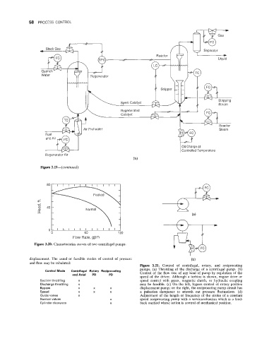
Figure 3.20. Characteristics curves of two centrifugal pumps.
displacement. The usual or feasible modes of control of pressure
and flow may be tabulated:
Figure 3.21. Control of centrifugal, rotary, and reciprocating
pumps. (a) Throttling of the discharge of a centrifugal pump. (b)
Control Mode Centrifugal Rotary Reciprocating
andhiat PD PD Control of the flow rate of any kind of pump by regulation of the
speed of the driver. Although a turbine is shown, engine drive or
Suction throttling X speed control with gears, magnetic clutch, or hydraulic coupling
Discharge throttling x may be feasible. (c) On the left, bypass control of rotary positive
Bypass X X X displacement pump; on the right, the reciprocating pump circuit has
Speed X X X a pulsation dampener to smooth out pressure fluctuations. (d)
Guide vanes X Adjustment of the length or frequency of the stroke of a constant
Suction valves X speed reciprocating pump with a servomechanism which is a feed-
Cylinder clearance X back method whose action is control of mechanical position.