
Page 82 - Chemical Process Equipment - Selection and Design
P. 82
54 PROCESS CONTROL
(a) Stirred tanks are used either as batch or continuous flow
Feed reactors. Heat transfer may be provided with an external heat
b exchanger, as shown on this figure, or through internal surface
or a jacket. Alternate modes of control may be used with the
controls shown: (i) When the HTM is on temperature control,
the pumparound will be on flow control; (ii) when the
pumparound is on temperature control, the HTM will be on
Flow flow control; (iii) for continuous overflow of product, the
Ratio control point for temperature may be on that line or in the
Control vessel; (iv) for batch operation, the control point for
temperature clearly must be in the vessel. Although level
control is shown to be maintained with an internal weir, the
product can be taken off with the pump on level control.
(b) This shows either direct or cascade control of the temperature
of a reactor with internal heat transfer surface and an internal
c weir. The sluggishly responding temperature of the vessel is
(a) Solvent - used to reset the temperature controuer of the HTM. For direct
control, the TC-2 is omitted and the control point can be on the
2 gases to be drawn off directly, thus eliminating need for the
HTM outlet or the product line or in the vessel.
the contents are boiling. The sketch shows temperature
-I---
maintenance by refluxing evolved vapors. A drum is shown
Raffinate € (e) Quite a uniform temperature can be maintained in a reactor if
from which uncondensed gases are drawn off on pressure
control, but the construction of the condenser may permit these
drum. The HTM of the condenser is on TC which resets the
PC if necessary in order to maintain the correct boiling
Reset
temperature in the reactor. Other modes of pressure control
are shown with the fractionator sketches of Figure 3.15 and on
Figure 3.5 dealing with vacuum control.
Ida (a) Flow reactors without mechanical agitation are of many
configurations, tanks or tubes, empty or containing fixed beds
Solvent of particles or moving particles. When the thermal effects of
reaction are substantial, multiple small tubes in parallel are
1 m used to provide adequate heat transfer surface. The sketch
shows a single tube provided with a jacket for heat transfer.
Feed to the reactor is on flow control, the effluent on pressure
control, and the flow of the HTM on temperature control of the
effluent with the possibility of reset by the composition of the
effluent.
(e) Heat transfer to high temperature reactions, above 300°C or so,
-m may be accomplished by direct contact with combustion gases.
The reaction tubes are in the combustion zone but safely away
from contact with the flame. The control mode is essentially
HTM similar to that for case (d), except that fuel-air mixture takes
the place of the HTM. The supply of fuel is on either
(C)
temperature or composition control off the effluent stream, and
the air is maintained in constant ratio with the fuel with the
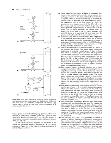
Figure 3.17. Some other controls on extraction towers. (a) Solvent flow ratio controller FRC.
flow rate maintained in constant ratio with the feed rate. (b) Solvent (fJ High temperature endothermic processes may need several
flow rate reset by controlled composition of raffinate. (c) reaction vessels with intermediate heat input. For example, the
Temperature of solvent or feed reset by the temperature at a inlet temperature to each stage of a catalytic reformer is about
control point in the tower.
975°F and the temperature drop ranges from about 100°F in the
first stage to about 15°F in the last one. In the two-stage
assembly of this figure, the input is on FC, the outlet of the last
reactor on PC, and the fuel supply to each furnace is on TC of
logic diagrams for normal and emergency operations, of the tasks its effluent, with the air supply on flow ratio control, as shown
involved in generating a computer system for a group of batch for example (e).
reactors in the book of Liptak (1973, pp. 536-565). Control of (g) Very effective heat transfer is accomplished by mixing of
discontinuous processes in general is treated in the book of Skrokov streams at different temperatures. The cumene process shown
(1980, pp. 128-163). here employs injection of cold reacting mixture and cold inert
In the present discussion, emphasis will be placed on the propane and water to prevent temperature escalation; by this
control of continuous reactors, concentrating on the several scheme, the inlet and outlet temperature are made essentially
examples of Figure 3.19 in the order of the letter designations of the same, about 500°F. Although not shown here, the main
individual figures used there. feed is, as usual for reactors, on FC and the outlet on PC. The