
Page 78 - Chemical Process Equipment - Selection and Design
P. 78
50 PROCESS CONTROL
M
(h) CONDENSATE
.c
+ I PF
HOT OIL HOT OIL
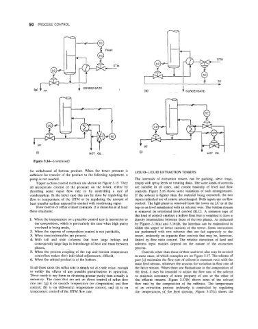
Figure 3.14-(continued)
for withdrawal of bottom product. When the tower pressure is LIQUID-LIQUID EXTRACTION TOWERS
sufficient for transfer of the product to the following equipment, a
pump is not needed. The internals of extraction towers can be packing, sieve trays,
Upper section control methods are shown on Figure 3.15. They empty with spray feeds or rotating disks. The same kinds of controls
all incorporate control of the pressure on the tower, either by are suitable in all cases, and consist basically of level and flow
throttling some vapor flow rate or by controlling a rate of controls. Figure 3.16 shows some variations of such arrangements.
condensation. In the latter case this can be done by regulating the If the solvent is lighter than the material being extracted, the two
flow or temperature of the HTM or by regulating the amount of inputs indicated are of course interchanged. Both inputs are on flow
heat transfer surface exposed to contact with condensing vapor. control. The light phase is removed from the tower on LC or at the
Flow control of reflux is most common. It is desirable in at least top or on level maintained with an internal weir. The bottom stream
these situations: is removed on interfacial level control (ILC). A common type of
this kind of control employs a hollow float that is weighted to have a
1. When the temperature on a possible control tray is insensitive to density intermediate between those of the two phases. As indicated
the composition, which is particularly the case when high punty by Figures 3.16(a) and 3.16(d), the interface can be maintained in
overhead is being made, either the upper or lower sections of the tower. Some extractions
2. When the expense of composition control is not justifiable, are performed with two solvents that are fed separately to the
3. When noncondensables are present, tower, ordinarily on separate flow controls that may be, however,
4. With tall and wide columns that have large holdup and linked by flow ratio control. The relative elevations of feed and
consequently large lags in interchange of heat and mass between solvents input nozzles depend on the nature of the extraction
phases, process.
5. When the process coupling of the top and bottom temperature Controls other than those of flow and level also may be needed
controllers makes their individual adjustments difficult, in some cases, of which examples are on Figure 3.17. The scheme of
6. When the critical product is at the bottom. part (a) maintains the flow rate of solvent in constant ratio with the
main feed stream, whatever the reasons for variation in flow rate of
In all these cases the reflux rate is simply set at a safe value, enough the latter stream. When there are fluctuations in the composition of
to nullify the effects of any possible perturbations in operation. the feed, it may be essential to adjust the flow rate of the solvent
There rarely is any harm in obtaining greater punty than actually is to maintain constancy of some property of one or the other of
necessary. The cases that are not on direct control of reflux flow the effluent streams. Figure 3.17(b) shows reset of the solvent
rate are: (g) is on cascade temperature (or composition) and flow flow rate by the composition of the raftinate. The temperature
control, (h) is on differential temperature control, and (i) is on of an extraction process ordinarily is controlled by regulating
temperature control of the HTM flow rate. the temperatures of the feed streams. Figure 3.17(c) shows the