
Page 76 - Chemical Process Equipment - Selection and Design
P. 76
48 PROCESS CONTROL
RESIDUUM
kCLT
TRIM Cur
HVGO
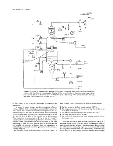
Figure 3.13. Crude oil vacuum tower. Pumparound reflux is provided at three lower positions as well as at
the top, with the object of optimizing the diameter of the tower. Cooling of the side streams is part of the
heat recovery system of the entire crude oil distillation plant. The cooling water and the steam for stripping
and to the vacuum ejector are on hand control.
off level control on the main tower, and return their vapors to the show the heat input to be regulated in these five different ways:
main tower.
A variety of control schemes are shown separately in Figures 1. On flow control of the heat transfer medium (HTM),
3.14 and 3.15 for the lower and upper sections of fractionators. To 2. On temperature control of the vapor leaving the reboiler or at
some extent, these sections are controllable independently but not some point in the tower,
entirely so because the flows of mass and heat are interrelated by 3. On differential pressure between key points in the tower,
the conservation laws. In many of the schemes shown, the top reflux 4. On liquid level in the bottom section,
rate and the flow of HTM to the reboiler are on flow controls. 5. On control of composition or some physical property of the
These quantities are not arbitrary, of course, but are found by bottom product.
calculation from material and energy balances. Moreover, neither
the data nor the calculation method are entirely exact, so that some Although only one of these methods can be shown clearly on a
adjustments of these flow rates must be made in the field until the particular sketch, others often are usable in combination with the
best possible performance is obtained from the equipment. In other controls that are necessary for completeness. In some cases
modern large or especially sensitive operations, the fine tuning is the HTM shown is condensing vapor and in other cases it is hot oil,
done by computer. but the particular flowsketches are not necessarily restricted to one
For the lower section of the fractionator, the cases of Figure 3.14 or the other HTM. The sketches are shown with and without pumps