
Page 75 - Chemical Process Equipment - Selection and Design
P. 75
3.3. EQUIPMENT CONTROL
DISTILLATION EQUIPMENT
As a minimum, a distillation assembly consists of a tower, reboiler,
condenser, and overhead accumulator. The bottom of the tower
serves as accumulator for the bottoms product. The assembly must
be controlled as a whole. Almost invariably, the pressure at either
the top or bottom is maintained constant; at the top at such a value
that the necessary reflux can be condensed with the available
coolant; at the bottom in order to keep the boiling temperature low
enough to prevent product degradation or low enough for the
available HTM, and definitely well below the critical pressure of the
bottom composition. There still remain a relatively large number of
variables so that care must be taken to avoid overspecifying the
number and kinds of controls. For instance, it is not possible to
control the flow rates of the feed and the top and bottom products
under perturbed conditions without upsetting holdup in the system.
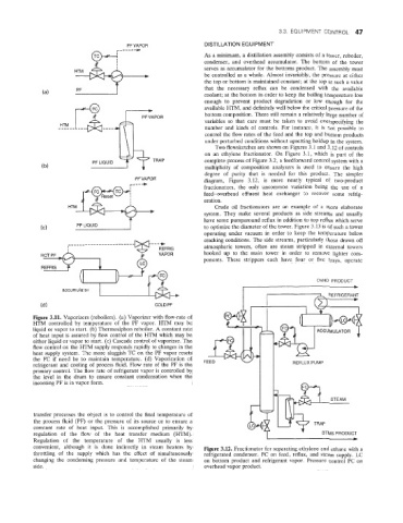
Two flowsketches are shown on Figures 3.1 and 3.12 of controls
on an ethylene fractionator. On Figure 3.1, which is part of the
- + TRAP complete process of Figure 3.2, a feedforward control system with a
PF LIQUID
multiplicity of composition analyzers is used to ensure the high
degree of purity that is needed for this product. The simpler
PF VAPOR diagram, Figure 3.12, is more nearly typical of two-product
-----c
fractionators, the only uncommon variation being the use of a
feed-overhead effluent heat exchanger to recover some refrig-
eration.
Crude oil fractionators are an example of a more elaborate
system. They make several products as side streams and usually
have some pumparound reflux in addition to top reflux which serve
to optimize the diameter of the tower. Figure 3.13 is of such a tower
operating under vacuum in order to keep the temperature below
~ --..- cracking conditions. The side streams, particularly those drawn off
___"__
I atmospheric towers, often are steam stripped in external towers
I
hooked up to the main tower in order to remove lighter com-
ponents. These strippers each have four or five trays, operate
OVHD PRODUCT
REFRIGERANT
c
(d) COLD PF
Figure 3.11. Vaporizers (reboilers). (a) Vaporizer with flow-rate of
HTM controlled by temperature of the PF vapor. HTM may be
liquid or vapor to start. (b) Thermosiphon reboiler. A constant rate
of heat input is assured by flow control of the HTM which may be
either liquid or vapor to1 start. (c) Cascade control of vaporizer. The
flow control on the WTlM supply responds rapidly to changes in the
heat supply system. The more sluggish TC on the PF vapor resets
the FC if need be io maintain temperature. (d) Vaporization of
refrigerant and cooling of process fluid. Flow rate of the PF is the FEED REFLUX PUMP
primary control. The flow rate of refrigerant vapor is controlled by
the level in the drum to ensure constant condensation when the
incoming PF is in vapor form.
transfer processes the object is to control the final temperature of
the process fluid (PF) or the pressure of its source or to ensure a t
constant rate of heat input. This is accomplished primarily by
regulation of the flow of the heat transfer medium (HTM). BTMS PRODUCT
Regulation of the temperature of the HTM usually is less I m
convenient, although it is done indirectly in steam heaters by Figure 3.12. Fractionator for separating ethylene and ethane with a
throttling of the suppiy which has the effect of simultaneously refrigerated condenser. FC on feed, reflux, and steam supply. LC
changing the condensing pressure and temperature of the steam on bottom product and refrigerant vapor. Pressure control PC on
side. overhead vapor product.