
Page 79 - Chemical Process Equipment - Selection and Design
P. 79
3.3. EQUIPMENT CONTROL 51
temperature of one of the streams to be controlled by TC-2 acting kind of system, the input conditions are noted, and calculations are
on the flow rate of the HTM, with reset by the temperature of a made and implemented by on-line computer of other changes that
control point in the tower acting through TC-I. When the effluents are needed in order to maintain satisfactory operation.
are unusually sensitive to variation of input conditions, it may be Mixer-settler assemblies for extraction purposes often are
inadvisable to wait for feedback from an upset of output preferable to differential contact towers in order to obtain very high
performance, but to institute feedforward control instead. In this extraction yields or to handle large flow rates or when phase
PF
PF
I I
I -.
I > ) I HTM
PF
ccs
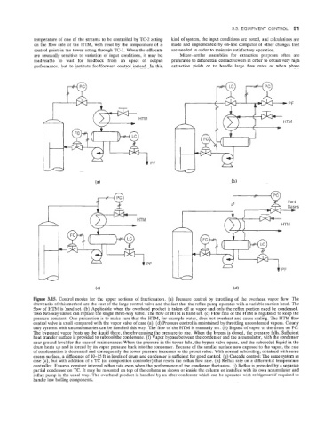
Figure 3.15. Control modes for the upper sections of fractionators. (a) Pressure control by throttling of the overhead vapor flow. The
drawbacks of this method are the cost of the large control valve and the fact that the reflux pump operates with a variable suction head. The
flow of HTM is hand set. (b) Applicable when the overhead product is taken off as vapor and only the reflux portion need be condensed.
Two two-way valves can replace the single three-way valve. The flow of HTM is hand set. (c) Flow rate of the HTM is regulated to keep the
pressure constant. One precaution is to make sure that the HTM, for example water, does not overheat and cause scaling. The HTM flow
control valve is small compared with the vapor valve of case (a). (d) Pressure control is maintained by throttling uncondensed vapors. Clearly
only systems with mcondensables can be handled this way. The flow of the HTM is manually set. (e) Bypass of vapor to the drum on PC
The bypassed vapor heats up the liquid there, thereby causing the pressure to rise. When the bypass is closed, the pressure falls. Sufficient
heat transfer surface is provided to subcool the condensate. (f) Vapor bypass between the condenser and the accumulator, with the condenser
near ground level for the ease of maintenance: When the pressure in the tower falls, the bypass valve opens, and the subcooled liquid in the
drum heats up and is forced by its vapor pressure back into the condenser. Because of the smaller surface now exposed to the vapor, the rate
of condensation is decreased and consequently the tower pressure increases to the preset value. With normal subcooling, obtained with some
excess surface, a difference of 10-15 ft in levels of drum and condenser is sufficient for good control. (g) Cascade control: The same system as
case (a), but with addition of a TC (or composition controller) that resets the reflux flow rate. (h) Reflux rate on a differential temperature
controller. Ensures constant internal reflux rate even when the performance of the condenser fluctuates. (i) Reflux is provided by a separate
partial condenser on TC. It may be mounted on top of the column as shown or inside the column or installed with its own accumulator and
reflux pump in the usual way. The overhead product is handled by an after condenser which can be operated with refrigerant if required to
handle low boiling components.