
Page 83 - Chemical Process Equipment - Selection and Design
P. 83
3.3. EQUIPMENT CONTROL 55
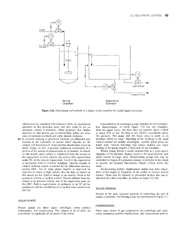
Heavy Phase
Mixing Separating
Chamber Chamber
Figure 3.18. Functioning and controls of a mixer-settler assembly for liquid-liquid extraction.
sidestrearns are regulated with hand-set valves by experienced Controllability of centrifugal pumps depends on their pressure-
operators in this particular plant, but they could be put on flow characteristics, of which Figure 3.20 has two examples.
automatic control if necessary. Other processes that employ With the upper curve, two flow rates are possible above a head
injection of cold process gas at intermediate points are some of about 65ft so that the flow is not reliably controllable above
cases of ammonia synthesis and sulfur dioxide oxidation. this pressure. The pump with the lower curve is stable at all
(h) In catalytic cracking of petroleum fractions, an influential side pressures within its range. Throttling of the discharge is the usual
reaction is the formation of carbon which deposits on the control method for smaller centrifugals, variable speed drives for
catalyst and deactivates it. Unacceptable deactivation occurs in larger ones. Suction throttling may induce flashing and vapor
about lOmin, so that in practice continuous reactivation of a binding of the pump. Figures 3.21(a) and (b) are examples.
portion of the catalyst in process must be performed. As shown Rotary pumps deliver a nearly constant flow at a given speed,
on this sketch, spent catalyst is transferred from the reactor to regardless of the pressure. Bypass control is the usual method, with
the regenerator on level control, and returns after regeneration speed control in larger sizes. Reciprocating pumps also may be
under TC off the reactor temperature. Level in the regenerator controlled on bypass if a pulsation damper is provided in the circuit
is maintained with an overflow standpipe. Smooth transfer of to smooth out pressure fluctuations; Figure 3.21(c) shows this
catalyst between vessels is assisted by the differential pressure mode.
control DPC, but in some plants transfer is improved by Reciprocating positive displacement pumps may have adjust-
injection of steam at high velocity into the lines as shown on ment of the length or frequency of the stroke as another control
this sketch for the input of charge to the reactor. Feed to the feature. These may be solenoid or pneumatic devices that can be
system as a whole is on flow control. Process effluent from the operated off a flow controller, as shown on Figure 3.21(d).
reactor is on pressure control, and of the regenerator gases on
the DPC. Fuel to regeneration air preheater is on TC off the
preheat air and the combustion air is on flow ratio control as in
part (e). SOLIDS FEEDERS
Several of the more common methods of controlling the rate of
supply of granular, free-flowing solids are represented in Figure 3.7.
LIQUID PUNIPS
COMPRESSORS
Process pumps are three types: clentrifugal, rotary positive
displacement, and reciprocating. The outputs of all of them are Three main classes of gas compressors are centrifugal and axial,
controliable by regulation of the speed of the driver. rotary continuous positive displacement, and reciprocating positive