
Page 87 - Chemical Process Equipment - Selection and Design
P. 87
3.3. EQUIPMENT CONTROL 59
pressor must be maintained above the magnitude at the peak in
pressure. Figure 3.23(c) shows an automatic bypass for surge
protection which opens when the principal flow falls to the critical
minimum; recycle brings the total flow above the critical.
Smaller rotary positive displacement compressors are con-
trolled with external bypass. Such equipment usually has a built-in
relief valve that opens at a pressure short of damaging the
equipment, but the external bypass still is necessary for smooth
control. Large units may be equipped with turbine or gas engine
drives which are speed adjustable. Variable speed gear boxes or
belt drives are not satisfactory. Variable speed dc motors also are
not useful as compressor drives. Magnetic clutches and hydraulic
couplings are used.
Reciprocating compressors may be controlled in the same way
as rotary units. The normal turndown with gasoline or diesel
engines is 50% of maximum in order that torque remains within
(dJ
Figure 3.21--(continued)
Throttling of the suction of centrifugal and axial compressors
wastes less power than throttling the discharge. Even less power is
wasted by adjustment of built-in inlet guide vanes with a
servomechanism which is a feedback control system in which the
controlled variable is mechanical position. Speed control is a
particularly effective control mode, applicable to large units that can
utilize turbine or internal combustion drives; control is by throttling
of the supply of motive fluids, steam or fuel.
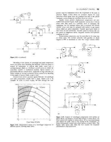
Characteristic curves-pressure against flowrate-f centrifugal
and axial compressors usually have a peak. Figure 3.22 is an
example. In order to avoid surging, the flow through the com-
m-
L
3
(D
(D
a,
L
a
i Limit (C)
motor drives. (a) Pressure control with turbine or motor drives. (b)
0 - d Figure 3.23. Control of centrifugal compressors with turbine or
5 10 Flow control with turbine or motor drives. SC is a servomechanism
Flow Rate, Vi Ib/hr that adjusts the guide vanes in the suction of the compressor. (c)
Surge and pressure control with either turbine or motor drive. The
Figure 3.22. Characteristic curves of a centrifugal compressor at bypass valve opens only when the Row reaches the minimum
different speeds, showing surge limits. calculated for surge protection.