
Page 92 - Chemical Process Equipment - Selection and Design
P. 92
64 DRIVERS FOR MOVING EQUIPMENT
hundred degrees of superheat. In larger sizes turbines may be with the enthalpies in Btu/lb. The efficiency is 9, off Figure 4.1, for
convenient sources of low pressure exhaust steam in the plant. example. The enthalpy change is that of an isentropic process. It
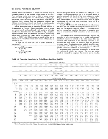
From multistage units, steam may be bled at several reduced may be calculated with the aid of the steam tables or a Mollier
pressures. When the expansion is to subatmospheric conditions, the diagram for steam. For convenience, however, special tables have
operation is called condensing because the exhaust steam must be been derived which give the theoretical steam rates for typical
condensed before removal from the equipment. Although the combinations of inlet and outlet conditions. Table 4.3 is an
efficiency of condensing turbines is less, there is an overall reduction abbreviated version.
of energy consumption because of the wider expansion range. Example 4.1 illustrates this kind of calculation and compares
Several parameters affect the efficiency of steam turbines, as the result with that obtained by taking the steam to behave as an
shown partially on Figure 4.1. Closer examination will need to take ideal gas. For nonideal gases with known PVT equations of state
into account specific mechanical details which usually are left to the and low pressure heat capacities, the method of calculation is the
manufacturer. Geared turbines [the dashed line of Fig. 4.l(b)] have same as for compressors which is described in that section of the
higher efficiencies, even with reduction gear losses, because they book.
operate with especially high bucket speeds. For example, for a On a Mollier diagram like that with Example 4.1, it is clear that
service of 500HP with 300psig steam, a geared turbine has an expansion to a low pressure may lead to partial condensation if
efficiency of 49.5% and one with a direct drive at 1800rpm has an insufficient preheat is supplied to the inlet steam. The final
efficiency of 24%. condition after application of the efficiency correction is the
The flow rate of steam per unit of power produced is pertinent one, even though the isentropic point may be in the
represented by two-phase region. Condensation on the blades is harmful to them
and must be avoided. Similarly, when carbon dioxide is expanded,
possible formation of solid must be guarded against.
When gases other than steam are employed as motive fluids,
the equipment is called a gas expander. The name gas turbine
usually is restricted to equipment that recovers power from hot
TABLE 4.3. Theoretical Steam Rates for Typical Steam Conditions (Ib/kWh)'
IC0 250 400 600 600 850 X50 YO0 YO0 1,200 I.250 1,250 1,450 1,450 1,800 2.400
Initial temp, "t'
365.9 500 650 750 825 X25 900 825 900 825 YO0 950 825 950 1000 1000
Iniri:il supchxt, '1
0 94.0 201.9 26l.Z 336.2 297.8 372.8 291.1 366.1 256.3 326.1 376.1 232.0 357.0 377.9 337.0
F.\haust Initial enthalpv, Ktiiilt,
presstire 1,195.5 1.26l.X 1.334.9 1,379.6 1,421.4 1,410.6 1,453.5 l,4OX.4 1,451.6 1,394.7 1.438.4 1,468.1 1,3X2.7 1,461.2 1,480.1 1,460.4
in€lg ~IJS
2.0 10.52 9.070 7.831 7.OX3 6.761 6..5xo 6.282 6.555 6.256 6.451 6. I33 5.944 6.408 5. Y(X) 5.6M 5.633
2.5 I0.XX 9. z43 X.017 i.251 6.9 16 6.723 6.41.5 6.696 6.388 6.584 6.256 6.061 6.536 6.014 5.773 5.733
3.0 11.20 9.582 x.217 7.396 i.052 6.847 6. 30 6.XIY 6.502 6.699 6.362 6.162 6.648 6.112 5.862 5.819
.5
4.0 11.76 Y.996 X.524 7.644 7.2X2 7.058 6.726 7.026 6.6% 6.XY.I 6.541 6.332 6.835 6.277 6.013 5.963
IlJiiIl~ gqc
5 21.69 16..57 13.01 I I .05 10.42 Y.838 9.288 9.755 9.209 9.397 R.XZO x.491 9.218 8.351 i.XN 7.713
IO 23.97 17.90 13.x3 11.64 10.95 10.30 9.705 10.202 9.617 9.797 ').IN) X.830 9.593 8.673 X.158 7.975
20 2X.6Z 20.44 15.31 I2.6X 11 .YO 11.10 10.43 10.98Z 10.327 10.4s1) 9.801 9.415 10.240 9.22; 8.642 8.421
10 33.69 22.95 16.73 13.63 12.75 I1.XO 1 1 .ox 11.67 IO. 9 .52 11.095 10.341 9.922 lO.XO1 9.70.1. 9.057 X.799
40 39.39 25.52 18.08 14.51 13.54 12.46 11.66 12.3OM 11.52 11.646 IO. x 3 I IO. 3 xo 11.309 10.134 9.427 9.136
50 46.00 2x.21 19.42 15.36 14.30 13.07 12.22 12.YO 12.06 12.16 l1.ZX-l IO.X(W 11.779 IO. 5 3 1 9.767 9.442
60 53.90 3 1.07 20.76 16.18 15.05 13.66 12.74 13.47 12.57 12.64 11.71 11.20 12.2-2 10.90 IO.0X 9.727
75 69.4 35.77 22.81 17.40 16.16 14.50 13.51 14.28 13.30 13.34 12.32 11.77 I?. 85 11.43 10.53 10.12
XO 75.9 37.47 23.51 I 7.80 16.54 14.78 13.77 14.53 13.55 13.56 12.52 11 .Y5 13.05 11.60 10.67 10.25
100 45.2 I 26.46 l9.4? 18.05 15.86 14.77 I5..5Y 14.50 14.42 13.27 12.65 13.83 12.24 11.21 10.73
125 57.XX 30.59 21.56 20.03 17.22 16.04 I6.Xi 15.70 15.46 14.17 13.51 14.76 13.01 1 l.X4 I I.2X
I50 76.5 35.40 23.x3 22.14 18.61 17.33 1X.18 16.91 16.47 15.06 14.35 15.65 13.75 12.44 I1.80
I60 86.X 37.57 24.79 23.03 19.17 17.85 18.71 17.41 16.XX 15.41 14.69 16.00 14.05 12.68 I 2.00
I75 41.16 26.29 24.43 20.04 18.66 19.52 1X.16 17.48 15.94 15.20 16.52 14.49 13.03 12.29
200 48.24 29.00 26.95 21.53 20.05 20.91 19.45 18.4X 16.84 16.05 17.39 15.23 13.62 12.77
250 69.1 35.40 32.89 24.78 23.OX 23.90 -37 74 20.57 lX.6X 17.81 19.11 16.73 14.78 13.69
300 43.72 40.62 28.50 26.53 27.27 25.37 22.79 20.62 19.66 20.89 18.28 15.95 14.59
400 72.2 67.0 38.05 35.43 35.71 33.22 27.X2 24.99 23.82 24.74 21.64 18.39 16.41
425 84.2 78.3 41.08 38.26 38.33 35.65 29.24 26.2 1 24.98 25.78 22.55 19.03 16.87
60() 78.5 73.1 68.11 63.4 42. IO 37.03 35.30 34.50 30. I6 24.06 20.29
~ ~ ~~
BFrom Theoretical Steam Rate Tables-Compatible with the 1967 ASME Steam Tables, ASME, 1969.