
Page 147 - Chemical Process Equipment - Selection and Design
P. 147
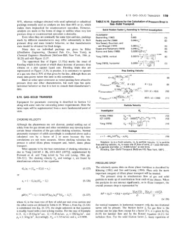
6.10. GAS-SOLID  TRANSFER  119
            95%  whereas voidages obtained with small spherical or cylindrical   TABLE 6.10.  Equations for the Calcusation of
                ~
            packings normally used as catalysts are less than 40% or so, which   Gas-Solid  Transport
            makes  them  impractical  for  countercurrent  operation.  However,
            catalysts are made in the forms of  rings or saddles when very low   Solid Friction Factor f According to Various Investigators
            pressure drop or countercurrent operation is desirable.   Investigator     t
                Even when they are nominally the same type and size, packings   Sternerding (1962)   0.003   (1)
            made  by  diffefferent  manufacturers  may  differ substantially in  their   Reddy and Pei (1969)   0.046U;’   (2)
            pressure  drop  and  mass  transfer  behavior,  so  that  manufacturers   Van Swaaij, Buurman, and
            data should be obtained for final design.            van Breugel (1970)    0.080 U,’             (3)
                Many  dala  on  individual  packings  are  given  by  Billet   Capes and Nakamura (1973)   0.048Ui3   (4)
            (Distillation Engineering,  Chemical  Pub.  Co.,  New  York),  in   Konno and Saito (1969)   0.0285VgD W,’   (5)
            Chemical  Engineers Handbook (McGraw-Hill, New York,  1984, p.   Yang (1978), vertical
            18.23) and with Figure 13.37.
                                                                                                -f]
                                                                                               [
                The  uppermost  line  of  Figure  13.37(a)  marks  the  onset  of           1 -E  (1 - E)U
            flooding which is the point at which sharp increase of  pressure drop   Yang (1976). horizontal   0.0293 7   (7)
                                                                                                 d/sD
                                                                                            E
            obtains  on  a  plot  against  liquid  rate.  Flooding  limits  also  are
            represented  OR Figure 13.36; in practice, it is customary to operate   Free Setting Velocity
            at a gas rate that is 70% of that given by the line, although there are
            many data points below this limit in this correlation.
                Mesh or other open structures as vessel packing have attractive
            pressure  drop  and  other  characteristics, but  each  type  has  quite            I( < 3.3
            individual behavior so that it is best to consult their manufacturer’s
            data.
                   S-SOLID  TRANSFE                                                             43.6<K<2360   (11)
            Equipment  fer  pneumatic  conveying  is  described  in  Section  5.2
            along with some rules for calculating power requirements. Here the     Particle Velocity
            latter topic will be supplemented from a more fundamental point of   ~
            view.                                                   Investigator
                                                                   Hinkle (1953)   ug - Uf                    (12)
                                                                                     - o,68~0.92 0.5  -0.2~-0.54
            CHOKING VELOCITY                                       IGT (1978)      9       P   PP  Pf   1     (13)
            Although  the  phenomena  are  not  clearcut,  partial  settling out  of   Yang (1976)            (14)
            solids from the gas stream and other instabilities may develop below
            certain linear velocities of  the gas called choking velocities. Normal   Voidage
            pneumatic transport of  solids accordingly is conducted above such a
            calculated  rate  by  a  factor  of  2  or  more  because  the  best
            correlations  are not  more  accurate.  Above  choking velocities the
            process is  called  dilute  phase  transport  and,  below,  dense phase   Notation: U, is a fluid velocity,  Up is particle velocity,  Ut is particle
            transport.                                          free settling velocity, m, is mass rate of flow of solid, 0 = pipe diameter,
                                                                Dp is particle diameter, g = 9.806 m/sec’  at sea level.
                What appears to be the best correlation of  choking velocities is   (Klinzing, Gas-Solid  Transport, McGraw-Hill, New York,  1981).
            due  to Yang  [AZChE J. 21,  1013-1015  (1975)], supplemented by
            Punwani  et  al.  and  Qang  (cited  by  Teo  and  Leung,  1984,  pp.
            520-521).  The  choking velocity  lJgc and  voidage  E,  are found  by
            simultaneous !solution of  the equations
                                                                PRESSURE DROP
                                                        (6.125)   The relatively sparse data on dense phase transport is described by
                                                                Klinzing (1981)  and  Teo  and  Leung  (1984). Here  only  the  more
                                                                important category of  dilute phase transport will be treated.
                                                                   The  pressure  drop  in  simultaneous  flow  of  gas  and  solid
                                                                particles is made up of contributions from each of  the phases. When
                                                                the particles do not interact significantly, as in dilute transport,  the
                                                                overall pressure drop is represented by
            and
                                                                                        2f   U.’L   2;sp  (I -E)UiL
                                                        (6.127)    AP=p,(l-E)Lg+p,sLg+~+            ~  D
                                                                                          D
                                                                                                           (6.128)
            where G, is the mass rate of  flow of  solid per unit cross section and
            the other terms are defined in Table 6.10. When   from Eq. (6.126)   for vertical transport; in horizontal transport only the two frictional
            is substituted into Eq. (6.127), the single unknown in that equation   terms  will  be  present.  The  friction  factor &  for  gas  flow  is  the
            is readily found with a root solving routine. For the case of Example   normal one for pipe flow; except for a factor of  4, it is given by Eq.
            6.15,  G, = 29.6 kg/m2 sec,  Ut = 0.45 m/sec,  p,  = 1282 kg/m3,  and   (6.19)  for  laminar  flow  and  by  the  Round  equation  (6.21)  for
            pg = 1.14 kgJm3. Accordingly, Ugc = 1.215 m/sec and  E,  = 0.9698.   turbulent  flow. For  the  solid friction factor J, many equations of