
Page 198 - Chemical Process Equipment - Selection and Design
P. 198
170 HEAT TRANSFER AND HEAT EXCHANGERS
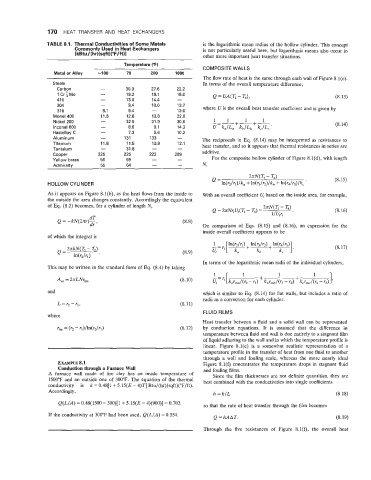
TABLE 8.1. Thermal Conductivities of Some Metals is the logarithmic mean radius of the hollow cylinder. This concept
Commonly Used in Heat Exchangers is not particularly useful here, but logarithmic means also occur in
[kBtu / (hr)(sqW"F/ft)l other more important heat transfer situations.
Temperature ("F)
COMPOSITE WALLS
Metal or Alloy -100 70 200 1000
The flow rate of heat is the same through each wall of Figure 8.l(c).
Steels In terms of the overall temperature difference,
Carbon - 30.0 27.6 22.2
1CrtMo - 19.2 19.1 18.0 (8.13)
41 0 - 13.0 14.4 -
304 - 9.4 10.0 13.7
316 8.1 9.4 - 13.0 where U is the overall heat transfer coefficient and is given by
Monel400 11.6 12.6 13.8 22.0
Nickel 200 - 32.5 31.9 30.6 (8.14)
lnconel 600 - 8.6 9.1 14.3
Hastelloy C - 7.3 5.6 10.2
Aluminum - 131 133 - The reciprocals in Eq. (8.14) may be interpreted as resistances to
Titaniu rn 11.8 11.5 10.9 12.1 heat transfer, and so it appears that thermal resistances in series are
Tantalum - 31.8 - -
Copper 225 225 222 209 additive.
Yellow brass 56 69 - - For the composite hollow cylinder of Figure 8.l(d), with length
Admiralty 55 64 - - N,
(8.15)
HOLLOW CYLINDER
As it appears on Figure 8.l(b), as the heat flows from the inside to With an overall coefficient Q based on the inside area, for example,
the outside the area changes constantly. Accordingly the equivalent
of Eq. (8.2) becomes, for a cylinder of length N, 2nN(T1 - T4)
Q = 2nNriUi(Tl - T4) = (8.16)
l/Qri '
dT
Q = -kN(2nr)-, dr
On comparison of Eqs. (8.15) and (8.16), an expression for the
inside overall coefficient appears to be
of which the integral is
(8.17)
In terms of the logarithmic mean radii of the individual cylinders,
This may be written in the standard form of Eq. (8.4) by taking
A, = ZnLNr,, (8.10)
and which is similar to Eq. (8.14) for flat walls, but includes a ratio of
radii as a correction for each cylinder.
L = r, - r,, (8.11)
FLUID FILMS
where
Heat transfer between a fluid and a solid wall can be represented
by conduction equations. It is assumed that the difference in
temperature between fluid and wall is due entirely to a stagnant film
of liquid adhering to the wall and in which the temperature profile is
linear. Figure 8.l(e) is a somewhat realistic representation of a
temperature profile in the transfer of heat from one fluid to another
through a wall and fouling scale, whereas the more nearly ideal
EXAMPLE 8.1 Figure 8.l(f) concentrates the temperature drops in stagnant fluid
Conduction through a Furnace Wall and fouling films.
A furnace wall made of fire clay has an inside temperature of Since the film thicknesses are not definite quantities, they are
1500°F and an outside one of 300°F. The equation of the thermal best combined with the conductivities into single coefficients
conductivity is k = 0.48[1 + 5.15(E - 4)T] Btu/(hr)(sqft)("F/ft).
Accordingly,
h = k/L (8.18)
Q(L/A) = 0.48(1500 - 300)[1+ 5.15(E - 4)(900)] = 0.703. so that the rate of heat transfer through the film becomes
If the conductivity at 300°F had been used, Q(L/A) = 0.554.
Q =MAT. (8.19)
Through the five resistances of Figure 8.l(f), the overall heat