
Page 194 - Chemical Process Equipment - Selection and Design
P. 194
166 FLUID TRANSPORT EQUIPMENT
Dischargeofstage 0 1 2 3 4
EXAMPLE 7.13 Torr 0.3 2.1 15.1 107 760
Interstage Condensers "F 14 63.7 127.4
A four-stage ejector is to evacuate a system to 0.3Torr. The
compression ratio in each stage will be The bubblepoint temperature in the second stage is marginal with
normal cooling tower water, particularly with the practical
restriction to 5°F below the bubblepoint. At the discharge of the
(P4/PO)*" = (760/0.3)1'4 = 7.09. third stage, however, either a surface or barometric condenser is
quite feasible. At somewhat higher process pressure, two interstage
The individual stage pressures and corresponding water bubblepoint condensers may be practical with a four-stage ejector, as indicated
temperatures from the steam tables are on Figure 7.31.
Nozzle Fnq Diffuser When barometric condensers are used, the effluent water
temperature should be at least 5°F below the bubblepoint at the
prevailing pressure. A few bubblepoint temperatures at low
StppE: > pressures are:
P- 3
Absolute (in. Hg) 0.2 0.5 1.0 2.0
Bubblepoint "F 34.6 58.8 79.0 101.1
Interstage pressures can be estimated on the assumption that
compression ratios will be the same in each stage, with the suction
to the first stage at the system pressure and the discharge of the last
stage at atmospheric pressure. Example 7.13 examines at what
stages it is feasible to employ condensers so as to minimize steam
usage in subsequent stages.
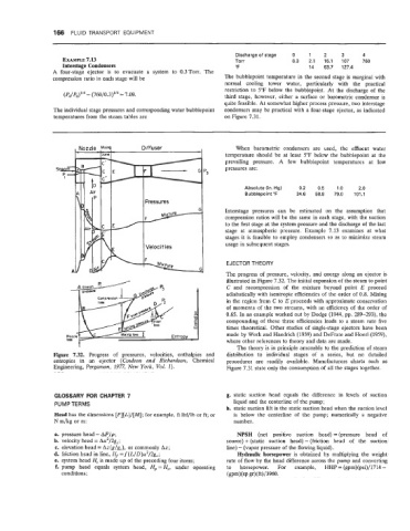
EJECTOR THEORY
The progress of pressure, velocity, and energy along an ejector is
illustrated in Figure 7.32. The initial expansion of the steam to point
C and recompression of the mixture beyond point E proceed
adiabatically with isentropic efficiencies of the order of 0.8. Mixing
in the region from C to E proceeds with approximate conservation
of momenta of the two streams, with an efficiency of the order of
0.65. In an example worked out by Dodge (1944, pp. 289-293), the
compounding of these three efficiencies leads to a steam rate five
times theoretical. Other studies of single-stage ejectors have been
made by Work and Haedrich (1939) and DeFrate and Hoerl(1959),
where other references to theory and data are made.
The theory is in principle amenable to the prediction of steam
Figure 7.32. Progress of pressures, velocities, enthalpies and distribution to individual stages of a series, but no detailed
entropies in an ejector (Coulson and Richardson, Chemical procedures are readily available. Manufacturers charts such as
Engineering, Pergumon, 1977, New York, Vol. 1). Figure 7.31 state only the consumption of all the stages together.
GLOSSARY FOR CHAPTER 7 g. static suction head equals the difference in levels of suction
PUMP TERMS liquid and the centerline of the pump;
h. static suction lift is the static suction head when the suction level
Head has the dimensions [F][L]/[M]; for example, ft lbf/lb or ft; or is below the centerline of the pump; numerically a negative
N m/kg or m: number.
a. pressure head = AP/p; NPSH (net positive suction head) = (pressure head of
b. velocity head = Au2/2g,; source) + (static suction head) - (friction head of the suction
c. elevation head = Az(g/gc), or commonly Az; line) - (vapor pressure of the flowing liquid).
d. friction head in line, Hf = f (L/D)u2/2g,; Hydraulic horsepower is obtained by multiplying the weight
e. system head H, is made up of the preceding four items; rate of flow by the head difference across the pump and converting
f. pump head equals system head, H,=H,, under operating to horsepower. For example, HHP = (gpm)(psi)/l714 =
conditions; (gm) (sp gr) (ft) /3960.