
Page 190 - Chemical Process Equipment - Selection and Design
P. 190
162 FLUID TRANSPORT EQUIPMENT
EXAMPLE 7.10 so that from Eq. (7.53),
Polytropic and Isentropic Temperatures
Take k = 1.4, (P,/P,) = 3, and qp = 0.75. From Eq. (7.34),
T 2 /T 1- - 30.3810 = 1.5198, isentropic,
(n - l)/n = (k - l)/kqp = 0.3810
and from Eq. (7.39) and from Eq. (7.54),
30.2857 -
%=-- 30.3810 - - 0'7094 T2/T, = 1 + (1/0.7094)(3°.2857 - 1) = 1.5197, polytropic.
7.7. EJECTOR AND VACUUM SYSTEMS EJECTOR ARRANGEMENTS
Application ranges of the various kinds of devices for maintenance Several ejectors are used in parallel when the load is variable or
of subatmospheric pressures in process equipment are shown in because the process system gradually loses tightness between
Table 7.3. The use of mechanical pumps-compressors in reverse- maintenance shutdowns-then some of the units in parallel are cut
for such purposes is mentioned earlier in this chapter. Pressures in or out as needed.
also can be reduced by the action of flowing fluids. For instance, Multistage units in series are needed for low pressures.
water jets at 40psig will sustain pressures of 0.5-2.0psia. For Sketches are shown in Figure 7.30 of several series arrangements. In
intermediate pressure ranges, down to O.1Torr or so, steam jet Figure 7.30(a), the first stage drives the process vapors, and the
ejectors are widely favored. They have no moving parts, are quiet, second stage drives the mixture of those vapors with the motive
easily installed, simple, and moderately economical to operate, and steam of the first stage. The other two arrangements employ
readily adaptable to handling corrosive vapor mixtures. A interstage condensers for the sake of steam economy in subsequent
specification form is in Appendix B. stages. In contact (barometric) condensers the steam and other
I
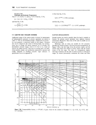
REDUCED PRESSURE, PR
Figure 7.29. Compressibility factors, z = PV/RT, of gases. Used for the solution of Example 7.11. PR =PIP,, TR = TIT,, and
V,. = P,V/RT,.