
Page 192 - Chemical Process Equipment - Selection and Design
P. 192
164 FLUID TRANSPORT EQUIPMENT
condensables are removed with a cold water spray. The tail pipes of such gases is the air leakage from the atmosphere into the system.
the condensers are sealed with a 34ft leg into a sump, or with a Theoretically, the leakage rate of air through small openings, if
condensate pump operating under vacuum. Surface condensers they can be regarded as orifices or short nozzles, is constant at
permit recovery of valuable or contaminating condensates or steam vessel pressures below about 53% of atmospheric pressure.
condensate for return as boiler feed. They are more expensive than However, the openings appear to behave more nearly as conduits
barometrics, and their design is more complex than that of other with relatively large ratios of lengths to diameters. Accordingly
kinds of condensers because of the large amounts of nonconden- sonic flow is approached only at the low pressure end, and the air
sables that are present. mass inleakage rate is determined by that linear velocity and the
As many as six stages are represented on Figure 7.30, low density prevailing at the vessel pressure. The content of other
combined with interstage condensers in several ways. Barometric gases in the evacuated vessel is determined by each individual
condensers are feasible only if the temperature of the water is below process. The content of condensables can be reduced by interposing
its bubblepoint at the prevailing pressure in a particular stage. a refrigerated condenser between process and vacuum pump.
Common practice requires the temperature to be about 5°F below Standards have been developed by the Heat Exchange Institute
the bubblepoint. Example 7.13 examines the feasibility of installing for rates of air leakage into commercially tight systems. Their chart
intercondensers in that process. is represented by the equation
AIR LEAKAGE rn = kVzm, (7.59)
The size of ejector and its steam consumption depend on the rate at
which gases must be removed from the process. A basic portion of where rn is in lb/hr, V is the volume of the system in cuft, and the
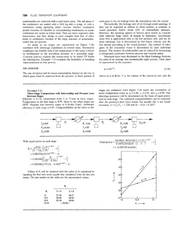
EXAMPLE 7.11 stages are estimated from Figure 7.29 under the assumption of
Three-Stage Compression with Intercooling and Pressure Loss equal compression ratios as zo = 0.98, z, = 0.93, and z, = 0.83. The
between Stages interstage pressures will be determined on the basis of equal power
Ethylene is to be compressed from 5 to 75 atm in three stages. load in each stage. The estimated compressibilities can be corrected
Temperature to the first stage is 60"F, those to the other stages are after the pressures have been found, but usually this is not found
100°F. Pressure loss between stages is 0.34 atm (5 psi). Isentropic necessary. k = C,/C, = 1.228 and (k - 1)/k = 0.1857.
efficiency of each stage is 0.87. Compressibilities at the inlets to the
-
To= 6OF P, 0.34
Po= 5 atm T, = 60
&=0.98 z, =0.93 ZpO.83
With equal power in each stage Total power = 3(0.98)(1.987)(520) 12.25 0.1857 - '1
0.1857(2545)0.87 [(T)
0 1857
= 1.34 HP/(lb mol/hr).
(k- 1)%
= 0.98(520)[(P1/5)0.1857 - 11 I I
0.1857
32 -
= 0.83(560){(75/(P, - 0.34)]0.1857 - 1)
Values of Pl will be assumed until the value of P2 calculated by
equating the first two terms equals that calculated from the last two
terms. The last entries in the table are the interpolated values.
e
s 1+2 2+3 -
p, -
12 27.50 28.31
12.5 29.85 28.94 27 I I
13.0 32.29 29.56 12 12.5 13
12.25 -28.6&