
Page 189 - Chemical Process Equipment - Selection and Design
P. 189
7.6. THEORY AND CALCULATIONS OF GAS COMPRESSION 761
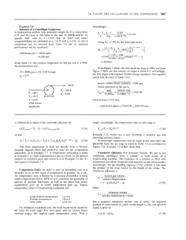
EXAMPLE 7.9 Accordingly,
Selection of a Centrifugal Compressor
A hydrocarbon mixture with molecular weight 44.23 is raised from n-1 k-1- Q.135
41°F and 20.1 psia to 100.5 psia at the rate of 2400 lb mol/hr. Its n - krlp - 1.135(0.77) = 0.1545.
specific heat ratio is k = 1.135 and its inlet and outlet
compressibiiities are estimated as z, = 0.97 and zz = 0.93. A size of Using Eq. (7.35) for the polytropic head,
compressor will be selected from Table 7.6 and its expected
performance will be calculated: n - l)/n
2400 Bb moli/hr = 1769 Ib/min,
1544
10,260 cfm = 0.95(-) 1.135 ( -)(501)[j0.1s4s - 11
0.135 44.23
From Table 7.6. the smallest compressor for this gas rate is # 38M. = 39430 ft.
Its characteristics are
From Figure 7.26(a), the max head per stage is 9700, and from
rb= 8100 rpm at 10-12 K ft/stage Figure 7.26(b) the min number of stages is about 4.5. Accordingly,
use five stages with standard 10,000 ft/stage impellers. The required
q, = 0.77
speed with the data of Table 7.6 is
speed = 8100~39430/10,000(5) = 7190 rpm.
----t 100.5
Power absorbed by the gas is
P, = 100.5
2, = 0.93
2, := 0.97 Friction losses -3% max;
1769 iblrnin
10260 cfm :. total power input = 2745/0.97 = 2830 MP max.
or alternately in terms of the isentropic efficiency by stages, accordingly, the compression ratio of each stage is
(7.54)
so that Example 7.11 works out a case involving a nonideal gas and
interstage pressure losses.
T2 = a, + (AT),/V, = Tl{l + (1/17,)[(q/Pl)(k-')/k - 1 I>. (7.55) In centrifugal compressors with all stages in the same shell, the
allowable head nse per stage is stated in Table 7.6 or correlated in
The final temperature is read off directly from a thermo- Figure 7.26. Example 7.9 utilizes these data.
dynamic diagram when that method is used for the compression
calculation, as in Example 7.7. A temperature calculation is made Volumetric Eficieney. For practical reasons, the gas is not
in Example 7.10. Such determinations also are made by the general completely discharged from a cylinder at each stroke of a
method for nonideal gases and mixtures as in Example 7.8 and for reciprocating machine. The clearance of a cylinder is filled with
ideal gases in Example 7.4. compressed gas which reexpands isentropically on the return stroke.
Accordingly, the gas handling capacity of the cylinder is less than
the product of the cross section by the length of the stroke. The
Compression Ratio, In order to save on equipment cost, it is volumetric efficiency is
desirable to use as few stages of compression as possible. As a rule,
the compression ratio is limited by a practical desirability to keep suction gas volume
outlet temperatures below 300°F or so to minimize the possibility of nu = cylinder displacement
ignition of machine lubricants, as well as the effect that power = 1 -L[(P2/5)'"G - 11, (7.57)
requirement goes up as outlet temperature goes up. Typical
compression ratios of reciprocating equipment are: where
clearance volume
= cylinder displacement volume .
Large pipeline compressors 1.2-2.0
Process cornpressors 1.5-4.0
Small units up to 6.0 For a required volumetric suction rate Q (cfm), the required
product of cross section A, (sqft), stroke length L, (ft), and speed N
For rninimiim equipment cost, the work requirement should be (rpm) is given by
the same for each stage. For ideal gases with no friction losses
between stages, this implies equal compression ratios. With n A,L,N= Q/%. (7.58)