
Page 201 - Chemical Process Equipment - Selection and Design
P. 201
8.2. MEAN TEMPERATURE DIFFERENCE 173
r Shell fluid
---is-
-4- Tube
fluid
0) BOTH FLUIDS CHANGING 01 COUNTERFLOW , NO PHASE
PHASE CHANGE
Shell fluid --l
bl ONE FLUID CHANGING I) ONE FLUID CHANGING
I fluid
PHASE PHASE
\
ci ONE FLUID CHANGING ONE FLUID CHANGING
PHASE PHASE
P
dl PARALLEL SLOW, NO CONDENSABLE AND
PHASE CHANGE NON- CONDENSABLE
COMPONENTS
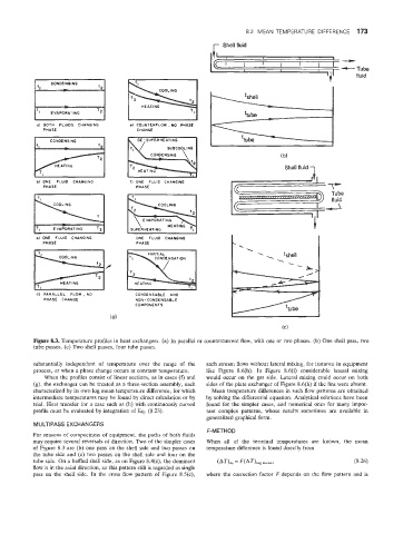
Figure 8.3. Ternperature profiles in heat exchangers. (a) In parallel or countercurrent flow, with one or two phases. (b) One shell pass, two
tube passes. (c) Two shell passes, four tube passes.
substantially independent of temperature over the range of the each stream flows without lateral mixing, for instance in equipment
process, or when a phase change occurs at constant temperature. like Figure 8.6(h). In Figure 8.6(i) considerable lateral mixing
When the profiles consist of linear sections, as in cases (f) and would occur on the gas side. Lateral mixing could occur on both
(g), the exchanger can be treated as a three-section assembly, each sides of the plate exchanger of Figure 8.6(h) if the fins were absent.
characterized by its own log mean temperature difference, for which Mean temperature differences in such flow patterns are obtained
intermediate temperatures may be found by direct calculation or by by solving the differential equation. Analytical solutions have been
trial. Heat transfer for a case such as (h) with continuously curved found for the simpler cases, and numerical ones for many impor-
profile must be evaluated by integration of Eq. (8.23). tant complex patterns, whose results sometimes are available in
generalized graphical form.
MULTIPASS EXCHANGERS
F-METHOD
For reasons of compactness of equipment, the paths of both fluids
may require several reversals of direction. Two of the simpler cases When all of the terminal temperatures are known, the mean
of Figure 8.3 are (b) one pass on the shell side and two passes on temperature difference is found directly from
the tube side and (c) two passes on the shell side and four on the
tube side. On a baffled shell side, as on Figure 8.4(c), the dominant (8.26)
flow is in the axial direction, so this pattern still is regarded as single
pass on the shell side. In the cross flow pattern of Figure 8.5(c), where the correction factor F depends on the flow pattern and is