
Page 205 - Chemical Process Equipment - Selection and Design
P. 205
8.2. MEAN TEMPERATURE DIFFERENCE 177
1.0 2.0 3.0 4.0 5.0 0
NTV
1.0
1.0
0.9
0.9
k kl
$0.8
m - I
5 0.8 -
"
m
0
c c 0.7
0.7
?! B
u. 0 0.6
0.6
0.5 0.5
0 0.1 0.2 0.3 0.4 0.5 0.6 0.7 0.8 0.9 1.0 0 0.1 02 0.3 0.4 0.5 0.6 0.7 0.8 0.9 1.0
K K
(9)
1.0 1.0
0.9 0.9
k
2 0.8 s- 0.8
m -
c Q
a
c r
0 0.7 2 0.7
e 'y
b
u B
0.6 0.6
0.5 0.5
I t ' I I 1 1 1 1 u It I III 8 I
0 0.1 0.2 0.3 0.4 0.5 0.6 0.7 0.8 0.9 1.0 0 0.1 0.2 0.3 0.4 0.5 0.6 0.7 0.8 0.9 1.0
K K
(i)
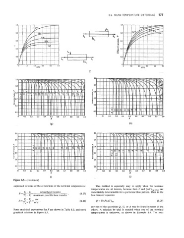
Figure 8.5--(continued)
expressed in terms of these functions of the terminal temperatures: This method is especially easy to apply when the terminal
temperatures are all known, because then F and (AT),ogmean are
pk3- actual heat transfer (8.27) immediately determinable for a particular flow pattern. Then in the
7'; - maximum possible heat itransfer ' heat transfer equation
=
U
R T-T, Q = UAF(AT), (8.29)
Tb-q m'c" (8.28)
any one of the quantities Q, U, or A may be found in terms of the
Some analytical expressions for F are shown in Table 8.3, and more others. A solution by trial is needed when one of the terminal
graphical solutioas in Figure 8.5. temperatures is unknown, as shown in Example 8.4. The next